Introduzione
This guide is not universal for the EBB boards. It is intended for Tiny Machines 3D customers that received a Vivedino Troodon with a CANbus toolhead!
Cosa ti serve
-
-
Tool board mount is mounted to the Turbiner, before mounting the EBB tool board to the EBB36 PCB Mount.
-
M3x8 SHCS
-
Clear Nylon washer
-
EBB36 PCB
-
M3 spacer
-
EBB PCB mount
-
-
-
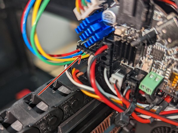
Molex Microfit 3.0 2x2 connector.
-
Brown wire-Ground
-
Green wire-Vcc
-
White wire CAN H
-
Yellow wire CAN L
-
-
-
Make sure the sensor cable is plugged into LDO Runout Sensor
-
Plug runout cable from the runout sensor into the port on the EBB PCB.
-
-
-
-
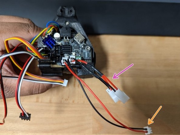
Hotend Fan – Heat sink fan and Extruder motor fan plug into fan splitter PCB
-
Cooling Part Fan – Both fans plug into y splitter
-
-
-
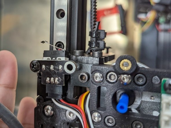
4 pin endstop cable
-
5v
-
Ground
-
The Signal Wire will be yellow OR white varies and is not important.
-
-
-
Loosen both screw terminals fully, then insert one wire at a time, fully tightening while holding the wire in place.
-
Connect Thermistor connector to TH0 port.
-


To reassemble your device, follow these instructions in reverse order.
To reassemble your device, follow these instructions in reverse order.

Team

4 Commenti
Erstmal eine super beschreibung! Die hilft mir sehr.
Top Beschreibung. Sollte mehr davon geben die sich solche Mühe machen.
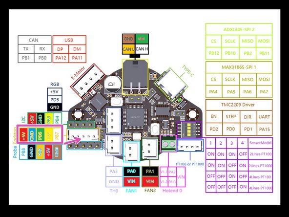
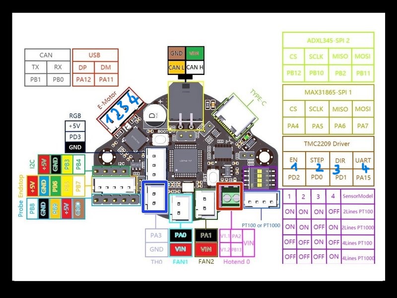
Sag mal der Anschluß für den E-Motor, sehe ich das richtig wenn man von links unten nach rechts oben die Pins klassifiziert.
EN=PD2 - STEP=PD0 - DIR=PD1 - UART=PA15
Link zum Bild wie ich das verstehe
https://www.gordonx.de/e-motor.jpg
Kannst du mir dazu die Kabelfarben vom Motor schicken !? Und der filament Sensor ist auf deinem Bild auch ein weißes Kabel auf PB7 zu sehen woher kommt das? Der filament sensor hat kein weißes Kabel !? Kleine Info Wäre prima.
Wenn nicht hier, dann super gerne per Mail: web@gordonx.de
Ich danke dir vielmals
For now, see https://github.com/bigtreetech/EBB/issue...
translated for others:
First of all, a great description! That helps me a lot. Great description. There should be more of those who make such an effort. Say the connection for the electric motor, I see that correctly if you classify the pins from the bottom left to the top right. EN=PD2 - STEP=PD0 - DIR=PD1 - UART=PA15 Link to the picture as I understand it https://www.gordonx.de/e-motor.jpg Can you send me the cable colors from the motor!? And the filament sensor can also be seen in your picture, a white cable on PB7 where does that come from? The filament sensor doesn't have a white cable!? A little info would be great. If not here, then feel free to email: web@gordonx.de Thank you very much.
I will look into adding another image BUT wire color should never be relied or used for pinout exclusively
I hadn't done that either. I looked exactly where which cable from the extruder motor goes. I just wanted to know whether the assignment of the orbiter is correct and where the white cable of the filament sensor goes. Ok, great thanks for the cable assignment of the motor.