Questa versione può contenere modifiche errate. Passa all'ultima istantanea verificata.
Cosa ti serve
-
Questo passaggio è privo di traduzione. Aiuta a tradurlo
-
Loosen the two screws on the battery panel. Then lift the panel up to remove it.
-
-
Questo passaggio è privo di traduzione. Aiuta a tradurlo
-
L Button.
-
Top of the battery pack.
-
To remove the battery pack, place your fingernail or a spudger at the top of the battery near the L button. Gently lift the battery out.
-
-
-
Ci sono due viti nascoste sotto i due gommini cerchiati in rosso.
-
Usa la punta dello spudger per estrarre i due gommini dal case inferiore.
-
-
-
-
Inserisci lo spudger tra il case inferiore e il pannello inferiore vicino all'angolo in alto a destra del DSi.
-
Passa delicatamente lo spudger lungo il margine del case esterno, creando uno spazio tra il case e il dispositivo.
-
Continua a passare lo spudger intorno al dispositivo fino a separare il case inferiore quasi del tutto.
-
-
Questo passaggio è privo di traduzione. Aiuta a tradurlo
-
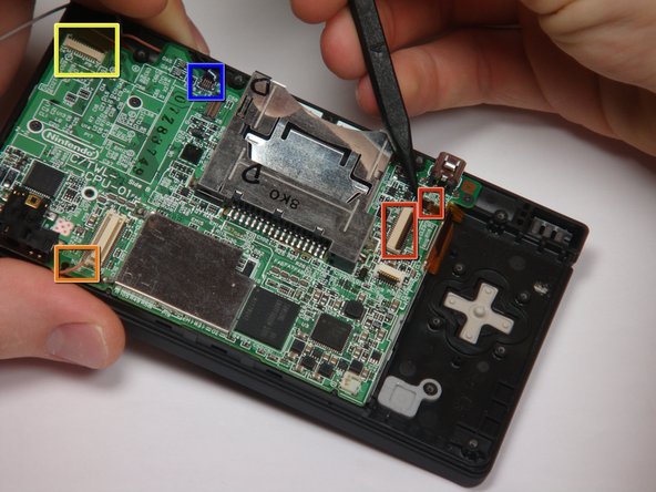
Pull the Wi-Fi board away from the motherboard by its edge closest to the headphone jack.
-
-
Questo passaggio è privo di traduzione. Aiuta a tradurlo
-
Pry the Wi-Fi antenna connector straight up from its socket on the Wi-Fi board.
-
-
Questo passaggio è privo di traduzione. Aiuta a tradurlo
-
Flip up the black latch and disconnect the D-Pad/Power Button ribbon cable.
-
-
Questo passaggio è privo di traduzione. Aiuta a tradurlo
-
The connector is two pieces -- a white "male" piece (connected to the wires), and a beige "female" part (soldered to the main board).
-
There is a small "notch" in the female part, to give you a place to insert a small flat-head screwdriver. Put the corner of your screwdriver in there, and twist it gently to push the white part up (away from the main board). Do not try to pull it to the right (towards the battery board).
-
-
Questo passaggio è privo di traduzione. Aiuta a tradurlo
-
If you have not already done so, disconnect the two bottom-LCD ribbon cables from the main board by prying up the black latches and pulling the cable out to the side.
-
The ribbon cable (marked in blue) for the touch screen is particularly thin and fragile; be careful to avoid bending it more than necessary.
-
Flip up the latch and remove the touch screen cable.
-
Flip up the latch and remove the top-screen ribbon cable.
-
Pry up on the orange cable to disconnect it from the main board, much like the antenna cable on the Wi-Fi module.
-