Salta al contenuto principale

Questa versione può contenere modifiche errate. Passa all'ultima istantanea verificata.

Cosa ti serve

  1. Questo passaggio è privo di traduzione. Aiuta a tradurlo

    : passo 1, immagine 1 di 2 : passo 1, immagine 2 di 2
    • Remove the battery cover and the battery

  2. Questo passaggio è privo di traduzione. Aiuta a tradurlo

    : passo 2, immagine 1 di 2 : passo 2, immagine 2 di 2
    • Remove the 7 silver screws with a Phillips #000 screw driver.

    • Sometimes the green one could be a little difficult. Use a tweezer for get it out.

  3. Questo passaggio è privo di traduzione. Aiuta a tradurlo

    : passo 3, immagine 1 di 3 : passo 3, immagine 2 di 3 : passo 3, immagine 3 di 3
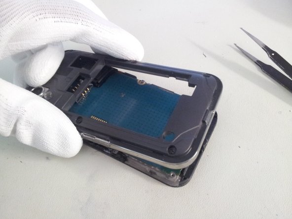
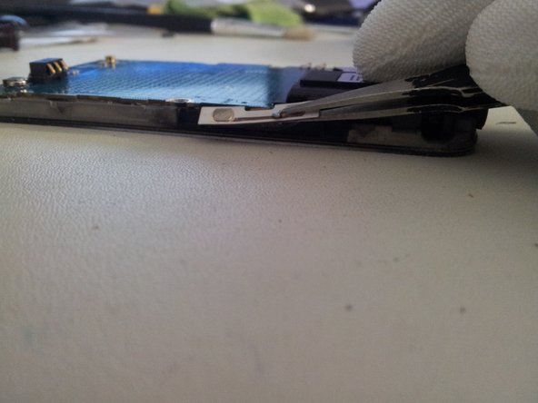
    • Lift gently the back cover from the screen assembly from the bottom.

  4. Questo passaggio è privo di traduzione. Aiuta a tradurlo

    : passo 4, immagine 1 di 2 : passo 4, immagine 2 di 2
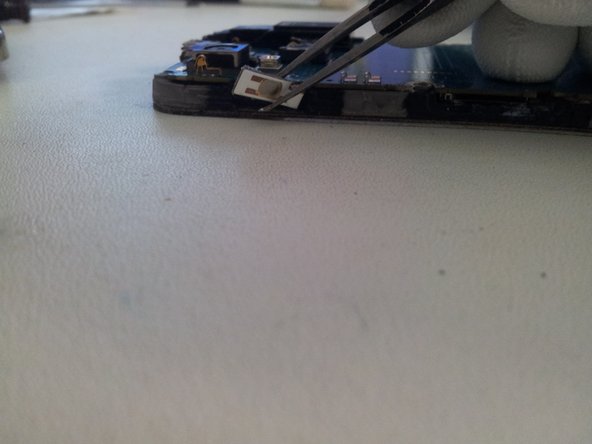
    • Use a flat tweezer for take off the flexible on/off button from the frame.

    • Be careful, the flexible is very delicate; it could be cut if you go too fast.

  5. Questo passaggio è privo di traduzione. Aiuta a tradurlo

    : passo 5, immagine 1 di 3 : passo 5, immagine 2 di 3 : passo 5, immagine 3 di 3
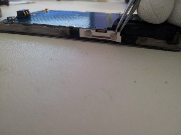
    • Use a flat tweezer and take off gently Flexible volume button from the left side.

    • Do the same for the right side.

    • Then lift the flex slowly, if you go fast you may cut the cable.

  6. Questo passaggio è privo di traduzione. Aiuta a tradurlo

    : passo 6, immagine 1 di 1
    • Lift the microphone from the logic board.

  7. Questo passaggio è privo di traduzione. Aiuta a tradurlo

    : passo 7, immagine 1 di 3 : passo 7, immagine 2 di 3 : passo 7, immagine 3 di 3
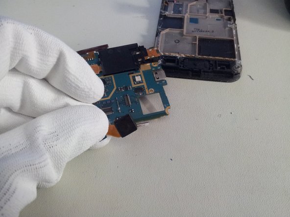
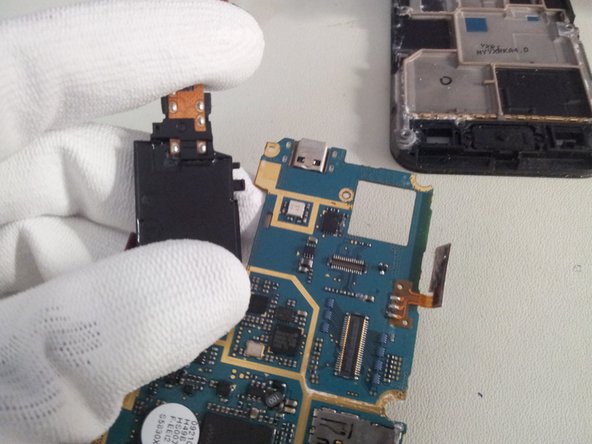
    • Lift the sensor/earpiece cable with the opening tool.

    • Don't force, you may damage the soldering.

  8. Questo passaggio è privo di traduzione. Aiuta a tradurlo

    : passo 8, immagine 1 di 3 : passo 8, immagine 2 di 3 : passo 8, immagine 3 di 3
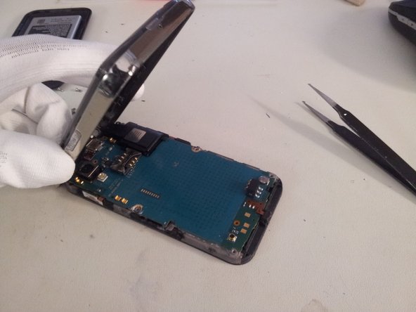
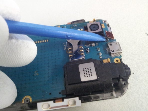
    • Lift the logic board from the right side.

    • Use the removal tool to unplug the display cable from the logic board.

    • You can now separate the Logic board from the display assembly.

  9. Questo passaggio è privo di traduzione. Aiuta a tradurlo

    : passo 9, immagine 1 di 2 : passo 9, immagine 2 di 2
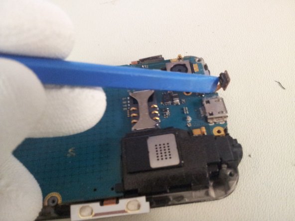
    • Use the removal tool to unclip the camera module from the Logic board.

  10. Questo passaggio è privo di traduzione. Aiuta a tradurlo

    : passo 10, immagine 1 di 3 : passo 10, immagine 2 di 3 : passo 10, immagine 3 di 3
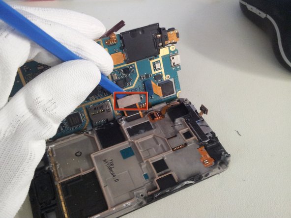
    • Use the removal tool or a spudger to unplug speaker module cable

    • And separate the speaker module from Logic board.

    • Be caution, the module is fixed by plastic teeth to the Logic board. Don't force, just make little wave-movements and the speaker comes on his own.

  11. Questo passaggio è privo di traduzione. Aiuta a tradurlo

    : passo 11, immagine 1 di 1
    • Now you can work with the Logic board.

Linea Traguardo

Altre 34 persone hanno completato questa guida.

finster

Membro da: 08/17/11

1.986 Reputazione

1 Guida realizzata

2 Commenti

Thanks for the post. This is really Helpful

Dave Dayanan - Replica

im curently selling one thx to you

Kyle at work - Replica

Aggiungi Commento

Visualizza Statistiche:

Ultime 24 Ore: 1

Ultimi 7 Giorni: 2

Ultimi 30 Giorni: 14

Tutti i Tempi: 26,700