Questa versione può contenere modifiche errate. Passa all'ultima istantanea verificata.
Cosa ti serve
-
Questo passaggio è privo di traduzione. Aiuta a tradurlo
-
Remove (2) 5 mm Phillips head screws attaching the small access panel to the base using a Phillips # 1 screwdriver.
-
-
Questo passaggio è privo di traduzione. Aiuta a tradurlo
-
Remove the small access panel using a heavy duty spudger.
-
-
Questo passaggio è privo di traduzione. Aiuta a tradurlo
-
Using the pull tab, pivot the solid-state drive bracket and peel off the bracket from the tabs on the computer base.
-
-
Questo passaggio è privo di traduzione. Aiuta a tradurlo
-
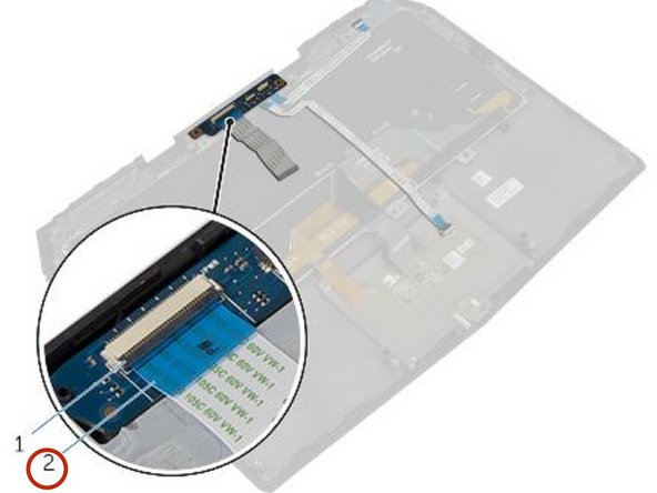
Using the pull tab, disconnect the solid-state drive cable from the system board.
-
-
Questo passaggio è privo di traduzione. Aiuta a tradurlo
-
Remove the screws that secure the solid-state drive assembly to the computer base.
-
-
Questo passaggio è privo di traduzione. Aiuta a tradurlo
-
Lift the solid-state drive assembly off the computer base.
-
Make sure the screws are off the solid-state assembly.
-
-
Questo passaggio è privo di traduzione. Aiuta a tradurlo
-
Slide and lift the solid-state drive off the solid-state assembly.
-
-
Questo passaggio è privo di traduzione. Aiuta a tradurlo
-
Slide the new solid-state drive into the solid-state drive assembly.
-
-
Questo passaggio è privo di traduzione. Aiuta a tradurlo
-
Replace the screw that secures the solid-state drive assembly with the screw holes on the computer base.
-
-
Questo passaggio è privo di traduzione. Aiuta a tradurlo
-
Align the screw holes on the solid-state drive assembly with the screw holes on the computer base.
-
-
Questo passaggio è privo di traduzione. Aiuta a tradurlo
-
Replace the screws that secure the solid-state drive assembly to the computer base.
-
-
Questo passaggio è privo di traduzione. Aiuta a tradurlo
-
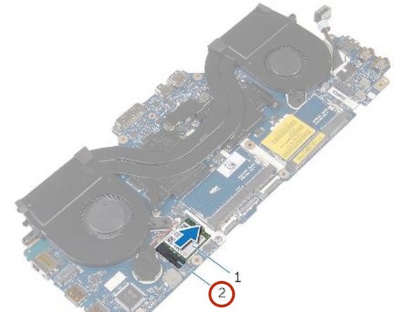
Connect the solid-state drive cable to the system board.
-
-
Questo passaggio è privo di traduzione. Aiuta a tradurlo
-
Align the screws on the solid-state drive bracket with the screw holes on the solid-state drive assembly.
-
-
Questo passaggio è privo di traduzione. Aiuta a tradurlo
-
Replace the screws that secure the solid-state drive bracket to the solid-state drive assembly.
-
-
Questo passaggio è privo di traduzione. Aiuta a tradurlo
-
Lift the latches and disconnect the keyboard and keyboard-backlight cables from the system board
-
-
-
Questo passaggio è privo di traduzione. Aiuta a tradurlo
-
Remove the screws that secure the palm-rest assembly to the computer base.
-
-
Questo passaggio è privo di traduzione. Aiuta a tradurlo
-
Lift the computer base slightly and push the release tabs on the palm-rest assembly until it pops out.
-
-
Questo passaggio è privo di traduzione. Aiuta a tradurlo
-
Turn the computer over and open the display as far as possible.
-
-
Questo passaggio è privo di traduzione. Aiuta a tradurlo
-
Using a plastic scribe, pry up along the edges of the palm-rest assembly.
-
-
Questo passaggio è privo di traduzione. Aiuta a tradurlo
-
Gently lift the palm-rest assembly and turn it over.
-
-
Questo passaggio è privo di traduzione. Aiuta a tradurlo
-
Lift the connector latch and disconnect the power-button board cable from the system board.
-
-
Questo passaggio è privo di traduzione. Aiuta a tradurlo
-
Remove the Keyboard.
-
Remove the power-button board.
-
Remove the status-light board.
-
Remove the touchpad.
-
-
Questo passaggio è privo di traduzione. Aiuta a tradurlo
-
Replace the touchpad.
-
Replace the status-light board.
-
Replace the power-button board.
-
Replace the keyboard.
-
-
Questo passaggio è privo di traduzione. Aiuta a tradurlo
-
Connect the power-button board cable to the system board.
-
-
Questo passaggio è privo di traduzione. Aiuta a tradurlo
-
Align the palm-rest assembly on the computer base and snap it into place.
-
-
Questo passaggio è privo di traduzione. Aiuta a tradurlo
-
Close the display and turn the computer over.
-
-
Questo passaggio è privo di traduzione. Aiuta a tradurlo
-
Replace the screws that secure the palm-rest assembly to the computer base.
-
-
Questo passaggio è privo di traduzione. Aiuta a tradurlo
-
Connect the keyboard cable and the keyboard-backlight cable to the system board.
-
-
Questo passaggio è privo di traduzione. Aiuta a tradurlo
-
Lift the connector latches and disconnect the touchpad cable and the status-light cable from the power-button board.
-
-
Questo passaggio è privo di traduzione. Aiuta a tradurlo
-
Peel the touchpad cable and status-light cable off the keyboard bracket.
-
-
Questo passaggio è privo di traduzione. Aiuta a tradurlo
-
Lift the keyboard bracket off the palm-rest assembly.
-
-
Questo passaggio è privo di traduzione. Aiuta a tradurlo
-
Remove the screws that secure the keyboard to the palm-rest assembly.
-
-
Questo passaggio è privo di traduzione. Aiuta a tradurlo
-
Slide and lift the keyboard, along with the cables, off the palm-rest assembly.
-
-
Questo passaggio è privo di traduzione. Aiuta a tradurlo
-
Align the screw holes on the NEW keyboard with the screw holes on the palm-rest assembly.
-
-
Questo passaggio è privo di traduzione. Aiuta a tradurlo
-
Replace the screws that secure the keyboard to the palm-rest assembly.
-
-
Questo passaggio è privo di traduzione. Aiuta a tradurlo
-
Align the screw holes on the keyboard bracket with the screw holes on the palm-rest assembly.
-
-
Questo passaggio è privo di traduzione. Aiuta a tradurlo
-
Replace the screws that secure the keyboard bracket to the palm-rest assembly.
-
-
Questo passaggio è privo di traduzione. Aiuta a tradurlo
-
Adhere the touchpad cable and status-light cable to the keyboard bracket.
-
-
Questo passaggio è privo di traduzione. Aiuta a tradurlo
-
Slide the touchpad cable and the status-light cable into their respective connectors on the power-button board and press down the latches to secure the cables.
-
-
Questo passaggio è privo di traduzione. Aiuta a tradurlo
-
Lift the connector latch and disconnect the power-button board cable from the power-button board.
-
-
Questo passaggio è privo di traduzione. Aiuta a tradurlo
-
Remove the screw that secures the power-button board to the palm-rest assembly.
-
-
Questo passaggio è privo di traduzione. Aiuta a tradurlo
-
Lift the power-button board off the palm-rest assembly.
-
-
Questo passaggio è privo di traduzione. Aiuta a tradurlo
-
Slide the power-button board cable into the power-button board connector and press down the latch to secure the cable.
-
-
Questo passaggio è privo di traduzione. Aiuta a tradurlo
-
Align the screw hole on the power-button board with the screw hole on the palm-rest assembly.
-
-
Questo passaggio è privo di traduzione. Aiuta a tradurlo
-
Replace the screw that secures the power-button board to the palm-rest assembly.
-
-
Questo passaggio è privo di traduzione. Aiuta a tradurlo
-
Slide the wireless card from the wireless-card slot on the system board.
-
-
Questo passaggio è privo di traduzione. Aiuta a tradurlo
-
Slide the wireless NEW card into the wireless-card slot on the system board.
-


Team
