Questa guida ha delle modifiche più recenti. Passa all'ultima versione non verificata.
Introduzione
In this guide, we will show you how to remove and replace the status light board.
Cosa ti serve
-
-
Loosen the captive screws that secure the base panel to the computer base.
-
-
-
Using a plastic scribe, gently release the tabs that secure the base panel to the computer base.
-
-
-
Disconnect the battery cable from the battery-cable connector.
-
Turn the computer over.
-
-
-
Press and hold the power button for 5 seconds to ground the system board.
-
-
-
Align the tabs on the base panel with the slots on the computer base and snap the base panel into place.
-
-
-
Tighten the captive screws that secure the base panel to the computer base.
-
-
-
Remove the screws that secure the solid-state drive bracket to the solid-state drive assembly.
-
-
-
Using the pull tab, pivot the solid-state drive bracket and peel off the bracket from the tabs on the computer base.
-
-
-
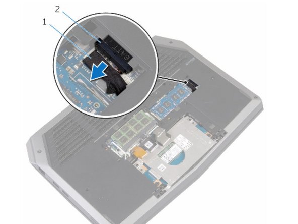
Using the pull tab, disconnect the solid-state drive cable from the system board.
-
-
-
Remove the screws that secure the solid-state drive assembly to the computer base.
-
-
-
Lift the solid-state drive assembly off the computer base.
-
-
-
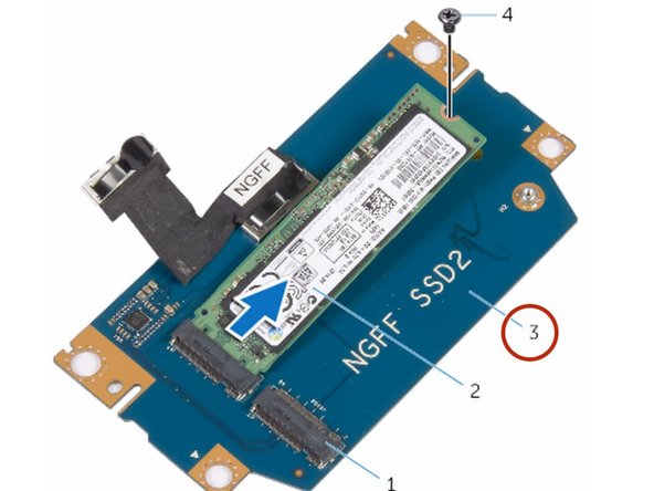
Remove the screw that secures the solid-state drive to the solid-state drive assembly.
-
-
-
Slide and lift the solid-state drive off the solid-state drive assembly.
-
-
-
Slide the NEW solid-state drive into the slot on the solid-state drive assembly.
-
-
-
Replace the screw that secures the solid-state drive to the solid-state drive assembly.
-
-
-
Align the screw holes on the solid-state drive assembly with the screw holes on the computer base.
-
-
-
Replace the screws that secure the solid-state drive assembly to the computer base.
-
-
-
-
Connect the solid-state drive cable to the system board.
-
-
-
Align the screw holes on the solid-state drive bracket with the screw holes on the solid-state drive assembly.
-
-
-
Replace the screws that secure the solid-state drive bracket to the solid-state drive assembly.
-
-
-
Lift the latches and disconnect the keyboard and keyboard-backlight cables from the system board.
-
-
-
Remove the screws that secure the palm-rest assembly to the computer base.
-
-
-
Lift the computer base slightly and push the release tabs on the palm-rest assembly until it pops out.
-
-
-
Turn the computer over and open the display as far as possible.
-
-
-
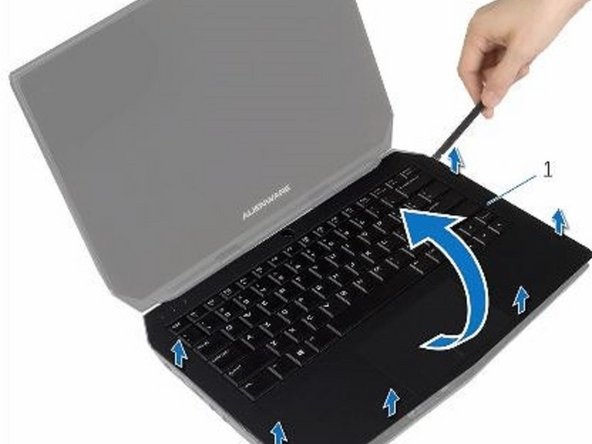
Using a plastic scribe, pry up along the edges of the palm-rest assembly.
-
-
-
Lift the connector latch and disconnect the power-button board cable from the system board.
-
-
-
Remove the keyboard.
-
Remove the power-button board.
-
Remove the status-light board.
-
Remove the Touchpad.
-
-
-
Replace the touchpad.
-
Replace the status-light board.
-
Replace the power-button board.
-
Replace the keyboard.
-
-
-
Connect the power-button board cable to the system board.
-
-
-
Align the palm-rest assembly on the computer base and snap it into place.
-
-
-
Replace the screws that secure the palm-rest assembly to the computer base.
-
-
-
Connect the keyboard cable and the keyboard-backlight cable to the system board.
-
-
-
Lift the connector latches and disconnect the touchpad cable and the status-light cable from the power-button board.
-
-
-
Peel the touchpad cable and status-light cable off the keyboard bracket.
-
-
-
Remove the screws that secure the keyboard bracket to the palm-rest assembly.
-
-
-
Remove the screws that secure the keyboard to the palm-rest assembly.
-
-
-
Slide and lift the keyboard, along with the cables, off the palm-rest assembly.
-
-
-
Align the screw holes on the NEW keyboard with the screw holes on the palm-rest assembly.
-
-
-
Replace the screws that secure the keyboard to the palm-rest assembly.
-
-
-
Align the screw holes on the keyboard bracket with the screw holes on the palm-rest assembly.
-
-
-
Replace the screws that secure the keyboard bracket to the palm-rest assembly.
-
-
-
Adhere the touchpad cable and status-light cable to the keyboard bracket.
-
-
-
Slide the touchpad cable and the status-light cable into their respective connectors on the power-button board and press down the latches to secure the cables.
-
-
-
Lift the connector latch and disconnect the status-light board cable from the status-light board.
-
-
-
Remove the screw that secures the status-light board to the palm-rest assembly.
-
-
-
Lift the status-light board off the palm-rest assembly.
-
-
-
Slide the status-light board cable into the status-light board connector and press down the latch to secure the cable.
-
-
-
Align the screw hole on the status-light board with the screw hole on the palm-rest assembly.
-
-
-
Replace the screw that secures the status-light board to the palm-rest assembly.
-


To reassemble your device, follow these instructions in reverse order.
To reassemble your device, follow these instructions in reverse order.

Team
