Questa versione può contenere modifiche errate. Passa all'ultima istantanea verificata.
Cosa ti serve
-
Questo passaggio è privo di traduzione. Aiuta a tradurlo
-
Remove (2) 5 mm Phillips head screws attaching the small access panel to the base using a Phillips # 1 screwdriver.
-
-
Questo passaggio è privo di traduzione. Aiuta a tradurlo
-
Remove the small access panel using a heavy duty spudger.
-
-
Questo passaggio è privo di traduzione. Aiuta a tradurlo
-
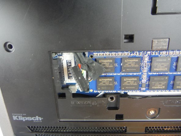
Disconnect the battery cable from the battery cable terminal.
-
-
Questo passaggio è privo di traduzione. Aiuta a tradurlo
-
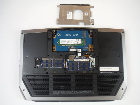
Remove (4) 6 mm Phillips head screws from the solid-state metal drive bracket, using a Phillips # 1 screwdriver.
-
-
Questo passaggio è privo di traduzione. Aiuta a tradurlo
-
Grab the pull tab to pivot the solid-state drive bracket upwards. Remove the bracket from the computer base.
-
-
Questo passaggio è privo di traduzione. Aiuta a tradurlo
-
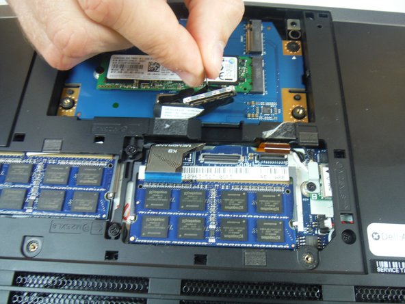
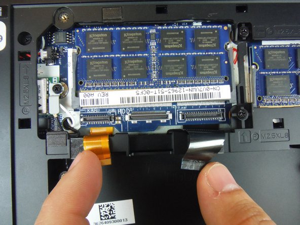
Using the pull tab, disconnect the black solid-state drive cable from the system board.
-
-
Questo passaggio è privo di traduzione. Aiuta a tradurlo
-
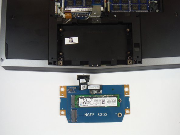
Remove (2) 3 mm Phillips head screws, using a Phillips # 0 screwdriver, that connect the solid-state drive assembly to the computer base.
-
-
Questo passaggio è privo di traduzione. Aiuta a tradurlo
-
Lift up on the solid-state drive assembly to remove it from the computer base.
-
-
-
Questo passaggio è privo di traduzione. Aiuta a tradurlo
-
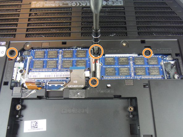
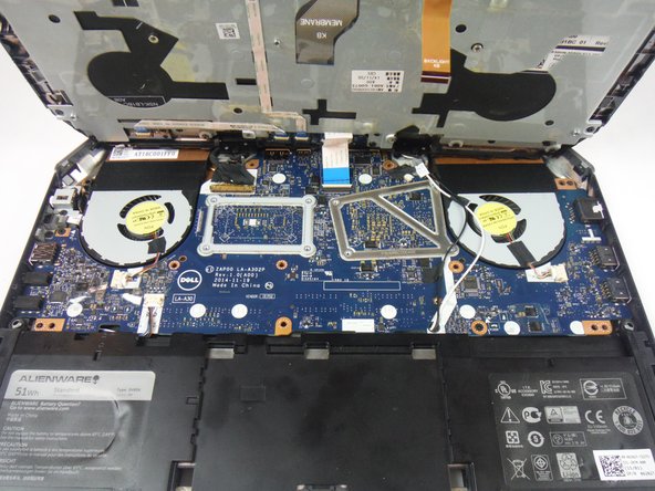
Locate two cables labeled, "KB Backlight" (orange) and "KB Membrane" (black). Lift up on the latches to disconnect the cables from the system board.
-
-
Questo passaggio è privo di traduzione. Aiuta a tradurlo
-
Remove (8) 9 mm Phillips head screws using a Phillips # 1 screwdriver, that secures the palm-rest assembly to the computer base.
-
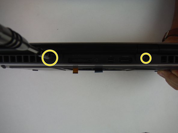
Remove (4) 8 mm Phillips head screws using a Phillips # 1 screwdriver.
-
Remove (2) 7 mm Phillips head screws using a Phillips # 1 screwdriver.
-
-
Questo passaggio è privo di traduzione. Aiuta a tradurlo
-
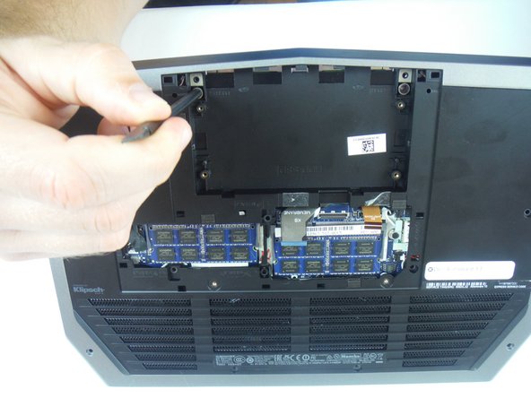
Lift the computer base slightly towards you and push the release tabs on the palm-rest assembly until it pops out using a spudger.
-
-
Questo passaggio è privo di traduzione. Aiuta a tradurlo
-
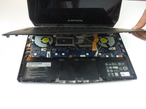
Turn the computer over and open the display as far as possible.
-
Using a plastic spudger, pry up along the edges of the palm-rest assembly.
-
Gently lift the palm-rest assembly.
-
-
Questo passaggio è privo di traduzione. Aiuta a tradurlo
-
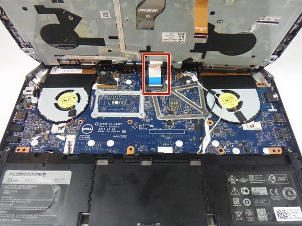
Lift the connector latch and disconnect the power-button board cable from the system board. Identified as a cable with a blue tab.
-
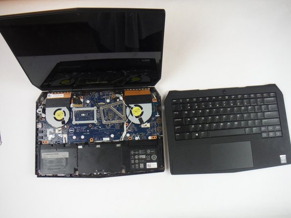
Lift the palm-rest assembly off the computer base.
-
-
Questo passaggio è privo di traduzione. Aiuta a tradurlo
-
Open the display as far as possible.
-
Remove (2) 3 mm Phillips head screws, using a Phillips head #0 screwdriver, that secure the hinge caps to the display hinges.
-
Slide and lift the hinge caps off the display hinges.
-
-
Questo passaggio è privo di traduzione. Aiuta a tradurlo
-
Close the display and turn the computer over.
-
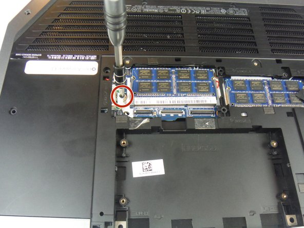
Remove (1) 2 mm Phillips head screw, using a Phillips head # 0 screwdriver, that secures the wireless-card bracket to the wireless card.
-
-
Questo passaggio è privo di traduzione. Aiuta a tradurlo
-
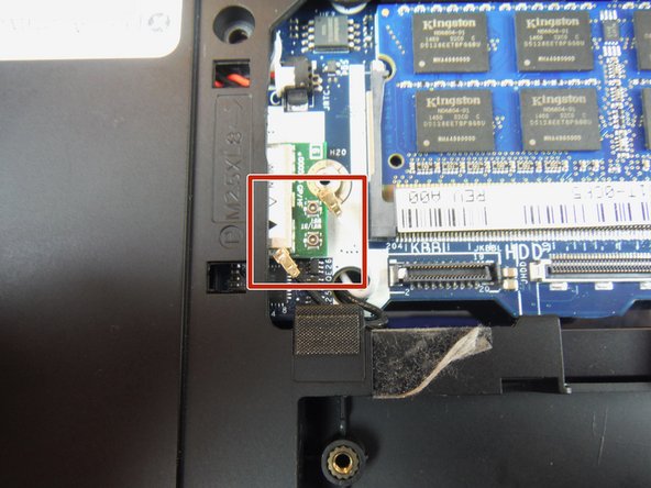
Disconnect the antenna cables from the wireless card using a heavy duty spudger. The wires can be removed by applying a force directed upward, away from the device.
-
-
Questo passaggio è privo di traduzione. Aiuta a tradurlo
-
Turn the computer over and open the display.
-
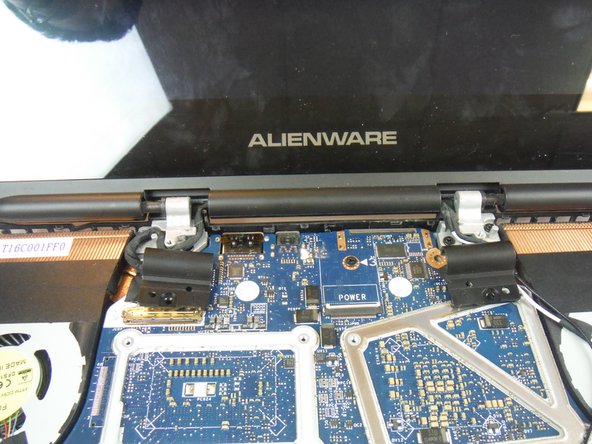
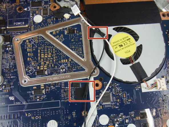
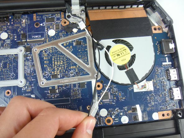
Peel off the adhesive tapes that secure the antenna cables to the system board.
-
-
Questo passaggio è privo di traduzione. Aiuta a tradurlo
-
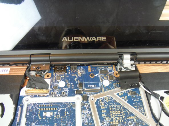
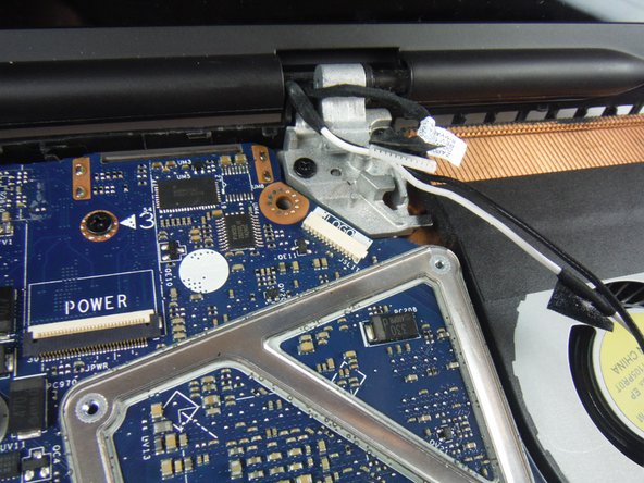
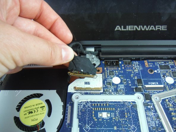
Lift the connector latch and disconnect the display cable from the system board.
-
Disconnect the logo-board cable from the system board.
-
Remove the antenna cables, display cable, and logo-board cable from the routing guides on the display hinges.
-
-
Questo passaggio è privo di traduzione. Aiuta a tradurlo
-
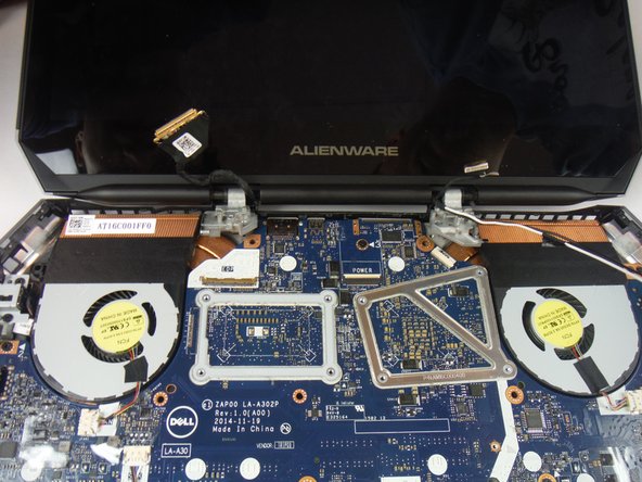
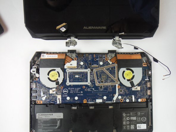
Remove (4) 8 mm Phillips head screws, using a Phillips # 1 screwdriver, that secure the display assembly to the computer base.
-
Lift the display assembly off the computer base.
-
-
Questo passaggio è privo di traduzione. Aiuta a tradurlo
-
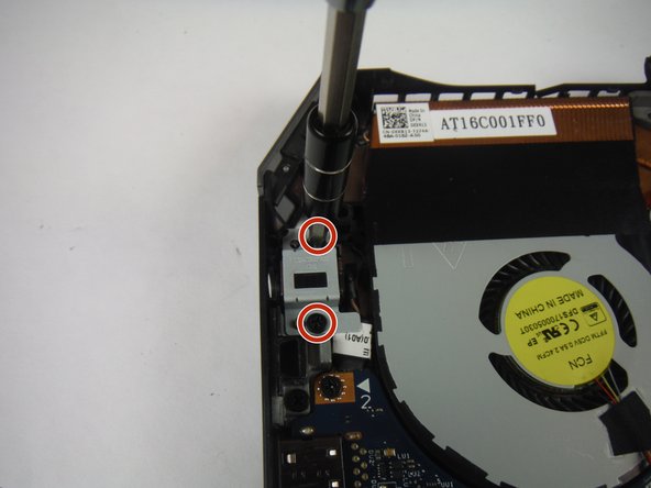
Remove the (2) 6 mm Phillips head screws securing the power adapter port bracket with a #1 Phillips screwdriver.
-
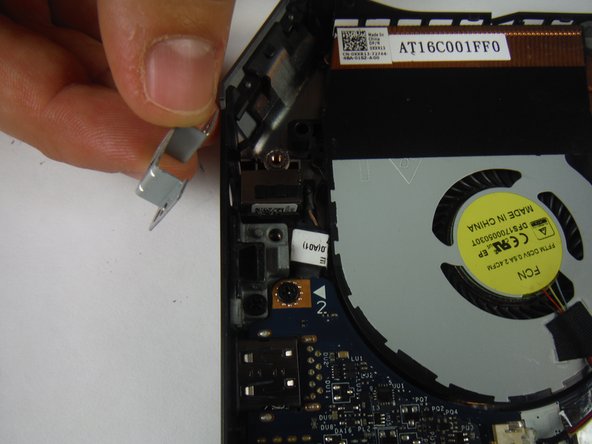
Lift and remove the power adapter port bracket.
-
-
Questo passaggio è privo di traduzione. Aiuta a tradurlo
-
Lift up and remove the power adapter port from the computer base.
-
-
Questo passaggio è privo di traduzione. Aiuta a tradurlo
-
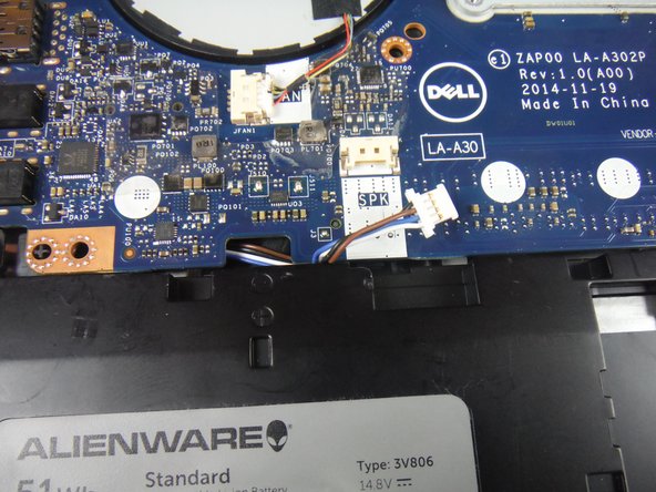
Disconnect the speaker cable connector from the service board.
-
-
Questo passaggio è privo di traduzione. Aiuta a tradurlo
-
Remove (3) 6 mm Phillips head screws securing the service board with a #1 Phillips screwdriver.
-
Lift up on the service board assembly using a heavy duty spudger and slide the board towards the battery to remove from the base.
-
-
Questo passaggio è privo di traduzione. Aiuta a tradurlo
-
Remove the speaker cable from the cable clip on the battery.
-
-
Questo passaggio è privo di traduzione. Aiuta a tradurlo
-
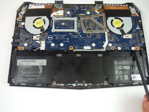
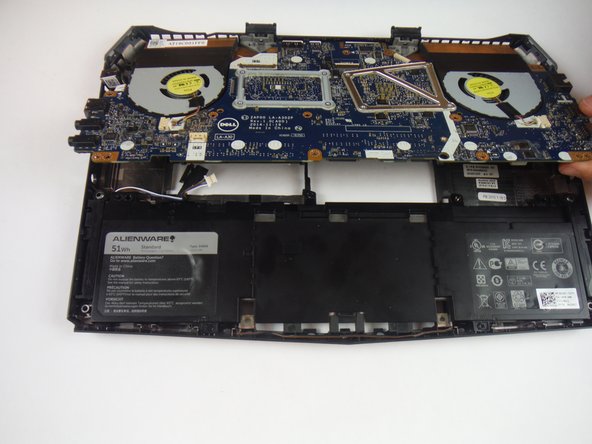
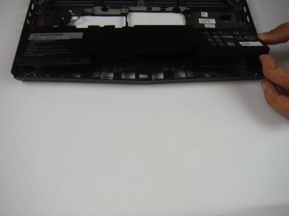
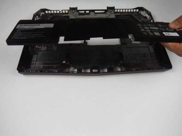
Remove (2) 6 mm Phillips head screws securing the battery to the computer base with a #1 Phillips screwdriver.
-
Lift up and remove the battery from the computer base.
-


Annulla: non ho completato questa guida.
Altre 4 persone hanno completato questa guida.

Team

USF Tampa, Team 14-2, Eyestone Fall 2016 Membro di USF Tampa, Team 14-2, Eyestone Fall 2016
USFT-EYESTONE-F16S14G2
3 Membri
7 Guide realizzate
2 Commenti
Please note, on slight variants of this. When battery is facing you with rear / hinge away. The right ide of motherboards has a clip cover on the USB C port, holding the motherboard down. Additionally, the 3x keyboard screws for lifting the palm rest were in the way. Almost every laptop i’ve EVER worked on for various dell/hp, ALWAYS have 2-4 screws for the keyboard. Please note this when writing tutorials as some models don’t open so easily. Be safe all, don’t rush things, and make sure you’re aware of what’s there proactively before ripping a laptop literally to pieces…
I did complete this guide, and it does work for the most part. See below my suggested updates/edits to improve. Thank you for making this guide. Helped a ton for initial perspective.