Questa versione può contenere modifiche errate. Passa all'ultima istantanea verificata.
Cosa ti serve
-
Questo passaggio è privo di traduzione. Aiuta a tradurlo
-
Remove the four (9 mm) screws with a PH2 screwdriver.
-
Remove the two (7 mm) located with a PH2 screwdriver.
-
-
Questo passaggio è privo di traduzione. Aiuta a tradurlo
-
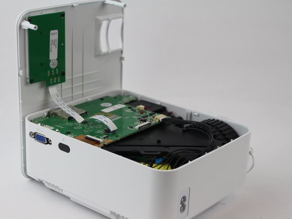
Flip the device over and pry the top off with a plastic opening tool.
-
-
Questo passaggio è privo di traduzione. Aiuta a tradurlo
-
Remove the ribbon cable connecting the motherboard to the button control board by gently pulling it from its connector.
-
-
-
Questo passaggio è privo di traduzione. Aiuta a tradurlo
-
Remove four (6 mm) screws connecting the motherboard using a J0 screwdriver.
-
-
Questo passaggio è privo di traduzione. Aiuta a tradurlo
-
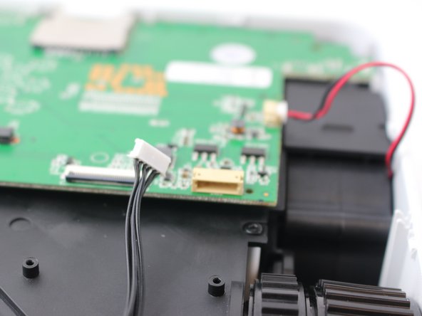
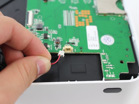
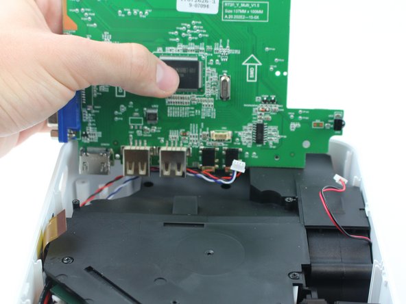
Remove the two cables connected to the motherboard: black power cable and the red/black fan cable.
-
-
Questo passaggio è privo di traduzione. Aiuta a tradurlo
-
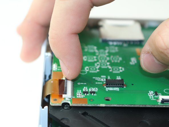
Lift the black latch on the ZIF connector and remove the ribbon cable that attaches the digitizer to the motherboard.
-
-
Questo passaggio è privo di traduzione. Aiuta a tradurlo
-
Raise motherboard by lifting sideways and then up to avoid the ports.
-
-
Questo passaggio è privo di traduzione. Aiuta a tradurlo
-
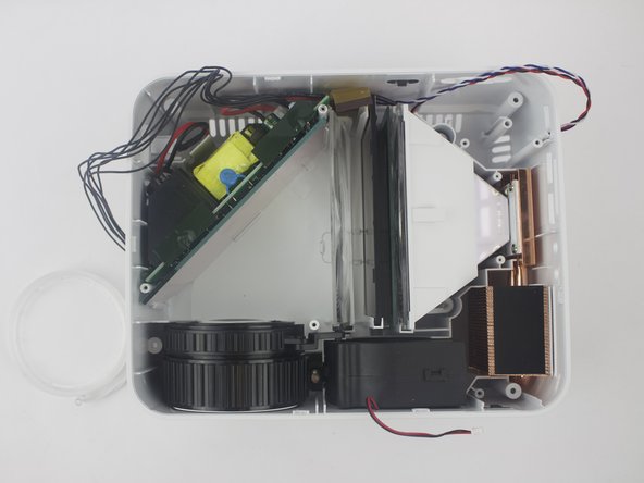
Remove wires attaching the piezoelectric speakers to the motherboard.
-
-
Questo passaggio è privo di traduzione. Aiuta a tradurlo
-
Remove the five screws securing the black plastic cover with a J0 screwdriver.
-
Lift up and out to remove.
-


Annulla: non ho completato questa guida.
Un'altra persona ha completato questa guida.
Team

USF Tampa, Team S16-G2, Boczar Spring 2018 Membro di USF Tampa, Team S16-G2, Boczar Spring 2018
USFT-BOCZAR-S18S16G2
5 Membri
5 Guide realizzate
4 Commenti
Anyone find a bulb for this thing? And/or know what else (or a quick fix) would fix a dark or burn mark on the image?
haing the same issue tried to call a electronics repair place to see if the could order a new polarizing lens for me and they said they could not unless they were the ones that did the repair
Really? Well, crap
How are the lenses supposed to sit in the hompow t20 mini projector