Introduzione
The factory installed 2.1 mm DC power socket is too short for the threads on the power cord to make a connection and screw the cord to the CPC800. By utilizing a longer DC power socket from Switchcraft (Manufacturer part number L722RA or DigiKey part number SC1331-ND), the power socket can be removed and replaced to work as intended with the power cord provided by Celestron. Soldering is required and it is assumed users are capable of performing this task.
This procedure will likely void your warranty and leave small scratches on the vertical forks and base plate around the DC socket.
Cosa ti serve
-
-
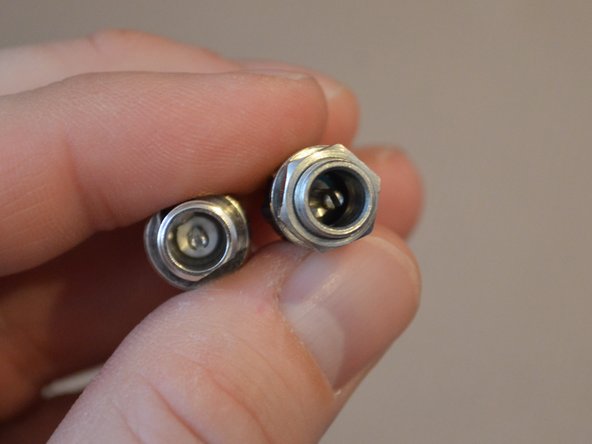
Confirm power cable fits properly in new 2.1mm DC power socket and will screw on properly.
-
Other photos shown of factory installed socket, which will not connect properly, and a comparison of the interior of the factory socket (left side) and the replacement socket (right side).
-
The replacement socket and the factory installed socket are the same size (2.1 mm) but may look different in the picture provided.
-
-
-
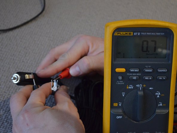
The ground pin is far back in the socket so it is easier to perform this task with the cable plugged into the socket. With the power cable inserted and tightly secured, locate and confirm with a meter which terminal on the back is the center pin and which is the outer ground pin.
-
This step is important! The center pin of the socket will connect to the red wire (positive 12 VDC) while the black wire (negative or ground) will connect to the outer pin. The same is true for the power plug - the center conductor is +12 VDC (red) and the outer conductor is Ground (black).
-
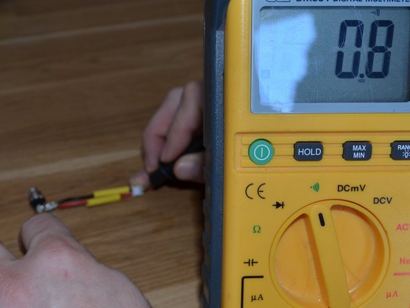
An open circuit (no continuity) is demonstrated by the OL notation on this digital multimeter.
-
-
-
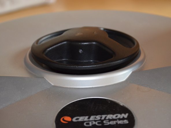
Make a note or take a picture of the knob's placement and distance above the base plate before removal. Also pay close attention to the number of rotations to remove the knob completely.
-
Locate the 2mm allen screw and remove completely. The locking knob should unscrew and be removed.
-
-
-
This step will likely leave some scratches on the lower portions of both telescope fork arms!
-
Remove the five 2.5mm allen screws from the base plate and slowly move the base plate up the fork arms as evenly as possible. The base plate shouldn't go any higher than you need to work inside of the unit without stretching the cables inside.
-
-
-
-
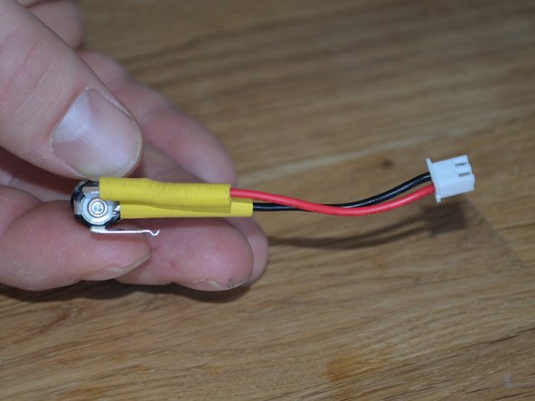
The red and black cables seen here connect to the DC power socket. The blue connectors will not be present on other units as this was a temporary fix until the proper parts could be ordered.
-
Make a note of the wire orientation (red and black wires) and connector since all units may not be the same. The connector can only insert in one direction. Also, note that the connector on this unit does not seem to push fully into the housing.
-
Disconnect the cable and unscrew the nut on the DC socket. The nut is recessed in the base plate and needle-nose pliers may be the best tool to use but it may scratch the base plate finish.
-
-
-
Loosely install the replacement DC power socket in the base plate hole. While holding the back of the socket to prevent rotation, screw on the nut to hold in place and confirm the power cord fits properly.
-
Note the location of the red and black wires on the factory installed DC power socket and then cut the wires close to the terminal points.
-
Strip the wire ends to an appropriate length to solder to the replacement socket. Ensure you know the location of the red and black wires on the new socket before soldering.
-
-
-
Place heat shrink or rubber tubing on wires before soldering then wrap the wire around the terminal for proper soldering.
-
Next, check to ensure you have continuity from the connector to the terminals. It is also good practice to check and make sure you do not have unwanted continuity between the other terminals.
-
Slide heat shrink or rubber tubing over solder points and heat or add electrical tape to ensure isolation.
-
-
-
Holding the back side of the replacement socket so that the terminals do not interfere with the moving parts, cables, or circuit boards, loosely tighten the nut to hold the socket in place.
-
Next, insert the wire connector in the same orientation as when it was removed.
-
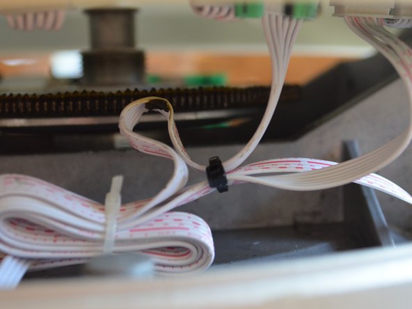
This is a good opportunity to relocate or tie wrap loose cables that may be too close to the gears inside the telescope.
-
-
-
Again, this step may leave scratches on the base plate.
-
Tighten the socket nut with needle-nose pliers or other tool.
-
Carefully plug in the power cord with a battery source connected and test to ensure the unit will turn on.
-
-
-
Gently push the base plate back into position making sure the plate does not get wedged sideways between the two fork arms. One side at a time works quite well. Also, make sure cabling stays away from the gears. Install the five 2.5 mm Allen screws and tighten.
-
Screw the lock knob all the way until it becomes tight and then loosen about half a turn (the knob should sit in the same location as noted in Step 3). Insert the 2 mm Allen screw in the knob and tighten (but not too tight).
-
Check for smooth operation and that the knob will lock and unlock the base of the telescope so that it will turn. If it does not work properly, either the knob is too loose or tight or the Allen screw in the knob is over tightened. The locking knob on the fork arm is a good reference of how the locking knob should operate.
-
-
-
Plug the unit into a 12 VDC power source, tighten the locking collar, and confirm proper operation.
-


Please add comments to improve this procedure.
Please add comments to improve this procedure.
Annulla: non ho completato questa guida.
Un'altra persona ha completato questa guida.
Documenti Allegati
7 Commenti
Just did this repair on the CPC 1100 which is basically the same base with a bigger optical tube. I had some issues. Like the original poster, I was having problems with my power cord maintaining a connection in the OEM socket. The original poster says “The factory installed 2.1 mm DC power socket is too short for the threads on the power cord to make a connection and screw the cord to the CPC800. “ I don’t believe the power cord on the CPC adapter is supposed to screw in. The 5amp one for the CPC Deluxe does. The Switchcraft socket recommended is bigger than the OEM socket. I had to drill out the hole in the base to get it to fit. The AC adapter I have plugs in and maintains a connection but isn’t’ as snug as I would like and it doesn’t screw in. The plug that goes to a cigarette lighter doesn’t fit now. I’m going to order the 5amp adapter for the CPC Deluxe and see if that works better. I’m going to have to find another plug for the cigarette plug cord.
I found another suggestion for the same problem that’s worth trying first. The pin inside the socket has a split down the middle. Some people have determined that the plug isn’t secure because the split in the pin is too narrow and as a result the pin is too thin to hold the adaptor on the plug. The solution is to take an x-acto knife and insert it into the split in the pin. That will bend the pin enough to widen it and make the socket hold the adapter securely.
I also carried out the center pin repair, by inserting a razor knife into the pin to split/bend the two halves outwards. This corrected the intermittent power on/off issues, at least temporarily. I also attached a small clamp on the nearest screw to tie off the power cord and act as a strain relief. The cord now pulls on the clamp, rather than the power socket, when the mount rotates. I have ordered a longer locking-style power socket, but this will work until I get a chance to replace it . Arguably a 2nd strain relief is still a good idea if you're pulling an extension cord from across your yard! (note to self - make sure there's lots of slack before alignment!)
By the way, while I had to cover off, I looked at the Aux1, 2, and Hand control connectors to see if I could turn one upside down (the wifi module sticks out and I fear it will catch and be broken) No easy way to turn the connectors as three are attached to one circuit board, and arranged in an arc, not a straight line.
I took a different, somewhat more complex route that gave good results. Instead of using a coaxial power connector, I decided to use a 4 pin XLR connector. These are commonly used for video/theater production intercom systems, and for DC power for professional TV cameras. They are inexpensive, easy to find, positive locking, have a built-in strain relief and extremely reliable. Follow the above instructions to take the base apart. But instead of simply opening the base, remove the base covercompletely by unplugging three connectors. Before doing this, use a felt tip marker to put a mark on one (but not both!) 6 pin connectors on the power board inside the lid (Has the power connector and the power switch going to it). Now, carefully disconnect all three connectors, and remove the top plate. Carefully mark and drill a large hole about 1 1/4 inches (30mm) from the front edhe of the area above the existing power connector. (continued)
Once big enough to accept a Switchcraft D4M or Neutrik NC4MP (I used the black versions)(Available from all the usual electronic parts sources, plus places like B&H photo, Markertek, etc.), mark and drill holes for the mounting screws. You can use 4-40 or 5-40 flat head screws, with matching nuts and star lockwashers )you can optionally use a flat washer under the lockwasher, but the nut alone has good coverage for strength purposes.) Install a wire from pin 1 of this connector to the black wire of the existing power connector at the jack. Install a second wire to pin 4 of the new connector, and attach to the red wire of the old connector.You have the option of leaving the old connector in circuit for compatability purposes, or remove it from the circuit to prevent accidental shorts, etc. leave the old jack n for appearance purposes. (continued)