Questa versione può contenere modifiche errate. Passa all'ultima istantanea verificata.
Cosa ti serve
-
Questo passaggio è privo di traduzione. Aiuta a tradurlo
-
Slide the grey latch to open the battery compartment.
-
-
Questo passaggio è privo di traduzione. Aiuta a tradurlo
-
Push and slide the orange retaining clip to the right to remove the battery.
-
-
Questo passaggio è privo di traduzione. Aiuta a tradurlo
-
Position the camera so that the bottom is facing up.
-
Remove the two 2.3mm screws beneath the name plate.
-
Remove the two 2.8 mm screws surrounding the threaded tripod mount.
-
-
Questo passaggio è privo di traduzione. Aiuta a tradurlo
-
Remove the 3.8mm screw from the back face of the camera.
-
-
Questo passaggio è privo di traduzione. Aiuta a tradurlo
-
Remove the two 2.3mm screws from the right face of the camera.
-
-
Questo passaggio è privo di traduzione. Aiuta a tradurlo
-
Remove the two outer 3.2mm screws from the left side of the camera
-
Remove the two inner 3.7mm screws from the left side of the camera.
-
-
Questo passaggio è privo di traduzione. Aiuta a tradurlo
-
Pull the back face panel away from the front end of the body. This may take some wiggling and force.
-
-
-
Questo passaggio è privo di traduzione. Aiuta a tradurlo
-
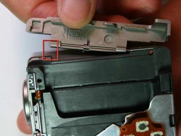
Remove the CF card door from the left side of the camera body.
-
-
Questo passaggio è privo di traduzione. Aiuta a tradurlo
-
Slide the rubber digital a/v cap out of place on the front plate.
-
-
Questo passaggio è privo di traduzione. Aiuta a tradurlo
-
Remove the rubber seal that covers the right side of the viewfinder.
-
-
Questo passaggio è privo di traduzione. Aiuta a tradurlo
-
Remove the two 3.9mm screws that hold the laminated copper sheet.
-
-
Questo passaggio è privo di traduzione. Aiuta a tradurlo
-
Remove the wire connections that connect along the bottom of the motherboard.
-
-
Questo passaggio è privo di traduzione. Aiuta a tradurlo
-
Remove the single 3.8mm screw that is on the motherboard.
-
-
Questo passaggio è privo di traduzione. Aiuta a tradurlo
-
Remove the motherboard from the main frame of the camera body.
-
-
Questo passaggio è privo di traduzione. Aiuta a tradurlo
-
After completing the removal of the motherboard, remove the tripod mounting screws (3.4mm) on the left side
-
-
Questo passaggio è privo di traduzione. Aiuta a tradurlo
-
Carefully pry the left side of the housing plate from the bottom of the tripod mounting plate, releasing it from the two alignment pegs next to the screws
-
-
Questo passaggio è privo di traduzione. Aiuta a tradurlo
-
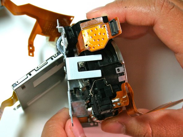
Lift the left side of the tripod mounting plate towards you, lift free the mounting plate from the rest of the assembly
-
Be careful because there are still wire connections attached to the mounting plate which you don't want to remove
-
-
Questo passaggio è privo di traduzione. Aiuta a tradurlo
-
Remove the 2.1mm screws from the bottom and top of the screen connecting it to the housing plate
-
-
Questo passaggio è privo di traduzione. Aiuta a tradurlo
-
Unsolder the four points at the top of the screen with a soldering iron
-
-
Questo passaggio è privo di traduzione. Aiuta a tradurlo
-
Remove the card-reader shield by removing the screw at the top of the shield.
-
-
Questo passaggio è privo di traduzione. Aiuta a tradurlo
-
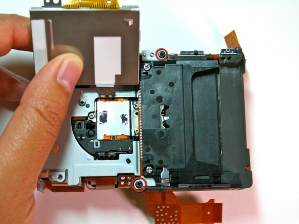
Remove the 2 black screws that attach the battery box to the housing plate.
-
-
Questo passaggio è privo di traduzione. Aiuta a tradurlo
-
Remove the three (3.1mm) black screws that were behind the screen and battery box.
-


Team

Cal Poly, Team 20-70, Walters Spring 2011 Membro di Cal Poly, Team 20-70, Walters Spring 2011
CPSU-WALTERS-S11S20G70
5 Membri
4 Guide realizzate