Questa versione può contenere modifiche errate. Passa all'ultima istantanea verificata.
Cosa ti serve
-
Questo passaggio è privo di traduzione. Aiuta a tradurlo
-
Unscrew five Phillips screws using a #0 Phillips screwdriver.
-
-
Questo passaggio è privo di traduzione. Aiuta a tradurlo
-
Open the memory card cover by moving the slide switch toward the top end of of the camera.
-
Remove the memory card from the slot.
-
-
Questo passaggio è privo di traduzione. Aiuta a tradurlo
-
Remove the rear cover from the rest of the camera.
-
-
Questo passaggio è privo di traduzione. Aiuta a tradurlo
-
Unscrew the four Phillips screws from the side of the casing and one screw from the bottom using a #0 Phillips screwdriver.
-
-
Questo passaggio è privo di traduzione. Aiuta a tradurlo
-
Free the front cover from the rest of the camera.
-
-
Questo passaggio è privo di traduzione. Aiuta a tradurlo
-
Unscrew two Phillips screws above the LCD using a #0 Phillips screwdriver.
-
-
Questo passaggio è privo di traduzione. Aiuta a tradurlo
-
Gently separate the top of LCD from the rest of the camera using your thumb.
-
Place the Spudger in the hole of the electrical ribbon.
-
Gently pull the ribbon down using the Spudger until it is free from the camera but still connected to the LCD.
-
-
Questo passaggio è privo di traduzione. Aiuta a tradurlo
-
Unscrew single Phillips screw with a #0 Phillips screwdriver.
-
Free the bottom panel and attached ribbon from the rest of the camera.
-
-
Questo passaggio è privo di traduzione. Aiuta a tradurlo
-
Turn over the camera.
-
Lift the clear plastic from the face of the camera, peeling the adhesive just below the zoom lens.
-
-
-
Questo passaggio è privo di traduzione. Aiuta a tradurlo
-
Place the Spudger between the orange ribbon and the black ribbon gate.
-
Lift the ribbon gate using the Spudger.
-
-
Questo passaggio è privo di traduzione. Aiuta a tradurlo
-
Place the Spudger in the corner of the ribbon above the hole.
-
Remove the ribbon from the ribbon gate by pulling the Spudger away from the gate.
-
-
Questo passaggio è privo di traduzione. Aiuta a tradurlo
-
Free this ribbon and the bottom panel from the rest of the camera.
-
-
Questo passaggio è privo di traduzione. Aiuta a tradurlo
-
Turn the camera over so you can see the LCD.
-
Remove single Phillips screw below the LCD using a #0 Phillips screwdriver.
-
-
Questo passaggio è privo di traduzione. Aiuta a tradurlo
-
Lift the blue ribbon gate using the Spudger.
-
-
Questo passaggio è privo di traduzione. Aiuta a tradurlo
-
Insert the Spudger into the hole of the ribbon.
-
Move the Spudger away from the gate to fully remove ribbon.
-
-
Questo passaggio è privo di traduzione. Aiuta a tradurlo
-
Lift the LCD away from the rest of the camera.
-
-
Questo passaggio è privo di traduzione. Aiuta a tradurlo
-
Lift off the capture button by wiggling it back and forth while pulling upward.
-
Be careful not to damage the two clips.
-
-
Questo passaggio è privo di traduzione. Aiuta a tradurlo
-
Flip open the four ribbon gates using the Spudger.
-
Gently pull out the ribbon cables from the gates using the Spudger.
-
-
Questo passaggio è privo di traduzione. Aiuta a tradurlo
-
Unscrew the four Phillips screws using a #0 Phillips screwdriver.
-
-
Questo passaggio è privo di traduzione. Aiuta a tradurlo
-
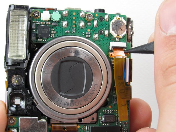
Gently lift the logic board.
-
Place the Spudger so that it is between the logic board, the white ribbon cable, and the rest of the camera.
-
Remove the white ribbon cable by pulling the Spudger away from the camera, keeping it parallel to the logic board.
-
-
Questo passaggio è privo di traduzione. Aiuta a tradurlo
-
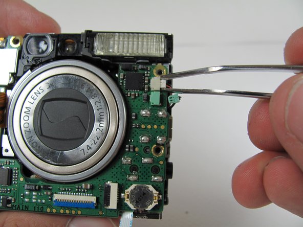
Lay the logic board back down so that it is resting on the body of the camera.
-
Pull the two plugs (white and green) out to the right from the logic board using the tweezers.
-
-
Questo passaggio è privo di traduzione. Aiuta a tradurlo
-
Desolder the two soldered ribbon cables attached to the logic board.
-
-
Questo passaggio è privo di traduzione. Aiuta a tradurlo
-
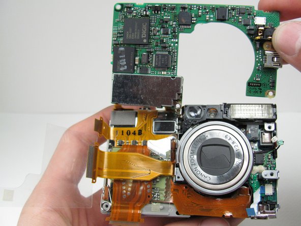
Free the logic board from the rest of the camera.
-
-
Questo passaggio è privo di traduzione. Aiuta a tradurlo
-
Blow the Particles out of the AV Port or USB Port using compressed air.
-
If the pins are damaged or missing, flip over the logic board and desolder the component from the logic board.
-


Team

Cal Poly, Team 16-28, Maness Winter 2010 Membro di Cal Poly, Team 16-28, Maness Winter 2010
CPSU-MANESS-W10S16G28
4 Membri
8 Guide realizzate