Questa versione può contenere modifiche errate. Passa all'ultima istantanea verificata.
Cosa ti serve
-
Questo passaggio è privo di traduzione. Aiuta a tradurlo
-
Take the LCD out of its place to expose the Phillips #PH00 screws.
-
Remove the two 2.5 mm Phillips #PH00 black screws on both sides of the LCD screen.
-
Next remove the two 3 mm Phillips #PH00 black screws near both sides of the base where the screen swivels.
-
-
Questo passaggio è privo di traduzione. Aiuta a tradurlo
-
Using a plastic opening tool, carefully pry off the back cover of the LCD.
-
-
Questo passaggio è privo di traduzione. Aiuta a tradurlo
-
Remove the 3 mm Phillips #PH00 silver screw on the side of the screen.
-
Turn the screen to remove the second 3 mm Phillips #PH00 silver screw.
-
-
Questo passaggio è privo di traduzione. Aiuta a tradurlo
-
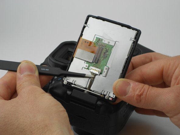
Using the tweezers, carefully disconnect the rear connector by pulling it away from the screen.
-
-
-
Questo passaggio è privo di traduzione. Aiuta a tradurlo
-
Now, four 2.2 mm Phillips #PH00 screws holding a cover around the hinge should be visible.
-
Turn the swivel around to expose the remaining of the aforementioned screws.
-
Then use the PH00 screw driver to remove them.
-
-
Questo passaggio è privo di traduzione. Aiuta a tradurlo
-
The eye piece will slide right off with a firm push upwards.
-
Remove the 3.4 mm Phillips #PH00 screw using a PH00 screw driver.
-
Remove the two 9.9 mm Phillips #PH00 screws using the PH00 screwdriver.
-
-
Questo passaggio è privo di traduzione. Aiuta a tradurlo
-
Using the PH00 screwdriver, remove the 3.8 mm Phillips #PH00 screw located on the back of the camera.
-
-
Questo passaggio è privo di traduzione. Aiuta a tradurlo
-
Using the plastic opening tool, carefully pull up the rubber grip around the port side of the camera.
-
Remove the four different sized screws located beneath the rubber grip.
-
6 mm Phillips #PH00 screw.
-
3.4 mm Phillips #PH00 screw.
-
3.9 mm Phillips #PH00 screw.
-
2.2 mm Phillips #PH00 screw.
-
-
Questo passaggio è privo di traduzione. Aiuta a tradurlo
-
Using the plastic opening tool, carefully pry off the the side cover.
-
-
Questo passaggio è privo di traduzione. Aiuta a tradurlo
-
Remove two 4.8 mm Phillips #PH00 screws from the memory card side of camera using the PH00 screwdriver.
-
-
Questo passaggio è privo di traduzione. Aiuta a tradurlo
-
Look at the bottom of the camera so the serial number tag reads up right.
-
Using the PH00 screw driver, remove the top three 3.5 mm Phillips #PH00 screws.
-
-
Questo passaggio è privo di traduzione. Aiuta a tradurlo
-
Now gently pull the back cover off the camera.
-
Gently pull the orange wire connected to the motherboard of the camera up and off of the motherboard.
-


Annulla: non ho completato questa guida.
Un'altra persona ha completato questa guida.
Team

USF Tampa, Team 16-6, Wollert Fall 2015 Membro di USF Tampa, Team 16-6, Wollert Fall 2015
USFT-WOLLERT-F15S16G6
3 Membri
14 Guide realizzate