Questa versione può contenere modifiche errate. Passa all'ultima istantanea verificata.
Cosa ti serve
-
Questo passaggio è privo di traduzione. Aiuta a tradurlo
-
Take the LCD out of its place to expose the Phillips #PH00 screws.
-
Remove the two 2.5 mm Phillips #PH00 black screws on both sides of the LCD screen.
-
Next remove the two 3 mm Phillips #PH00 black screws near both sides of the base where the screen swivels.
-
-
Questo passaggio è privo di traduzione. Aiuta a tradurlo
-
Using a plastic opening tool, carefully pry off the back cover of the LCD.
-
-
Questo passaggio è privo di traduzione. Aiuta a tradurlo
-
Remove the 3 mm Phillips #PH00 silver screw on the side of the screen.
-
Turn the screen to remove the second 3 mm Phillips #PH00 silver screw.
-
-
Questo passaggio è privo di traduzione. Aiuta a tradurlo
-
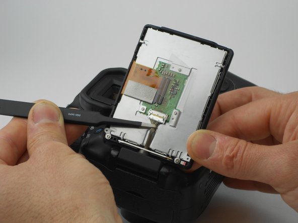
Using the tweezers, carefully disconnect the rear connector by pulling it away from the screen.
-
-
Questo passaggio è privo di traduzione. Aiuta a tradurlo
-
Now, four 2.2 mm Phillips #PH00 screws holding a cover around the hinge should be visible.
-
Turn the swivel around to expose the remaining of the aforementioned screws.
-
Then use the PH00 screw driver to remove them.
-
-
-
Questo passaggio è privo di traduzione. Aiuta a tradurlo
-
The eye piece will slide right off with a firm push upwards.
-
Remove the 3.4 mm Phillips #PH00 screw using a PH00 screw driver.
-
Remove the two 9.9 mm Phillips #PH00 screws using the PH00 screwdriver.
-
-
Questo passaggio è privo di traduzione. Aiuta a tradurlo
-
Using the PH00 screwdriver, remove the 3.8 mm Phillips #PH00 screw located on the back of the camera.
-
-
Questo passaggio è privo di traduzione. Aiuta a tradurlo
-
Using the plastic opening tool, carefully pull up the rubber grip around the port side of the camera.
-
Remove the four different sized screws located beneath the rubber grip.
-
6 mm Phillips #PH00 screw.
-
3.4 mm Phillips #PH00 screw.
-
3.9 mm Phillips #PH00 screw.
-
2.2 mm Phillips #PH00 screw.
-
-
Questo passaggio è privo di traduzione. Aiuta a tradurlo
-
Using the plastic opening tool, carefully pry off the the side cover.
-
-
Questo passaggio è privo di traduzione. Aiuta a tradurlo
-
Remove two 4.8 mm Phillips #PH00 screws from the memory card side of camera using the PH00 screwdriver.
-
-
Questo passaggio è privo di traduzione. Aiuta a tradurlo
-
Look at the bottom of the camera so the serial number tag reads up right.
-
Using the PH00 screw driver, remove the top three 3.5 mm Phillips #PH00 screws.
-
-
Questo passaggio è privo di traduzione. Aiuta a tradurlo
-
Now gently pull the back cover off the camera.
-
Gently pull the orange wire connected to the motherboard of the camera up and off of the motherboard.
-
-
Questo passaggio è privo di traduzione. Aiuta a tradurlo
-
Carefully pry off the LCD screen connector up from the motherboard to disconnect it, using the plastic opening tool.
-
-
Questo passaggio è privo di traduzione. Aiuta a tradurlo
-
Remove one 2.8 mm Phillips #PH00 black screw on the side of the swivel assembly by using the PH00 screwdriver.
-
-
Questo passaggio è privo di traduzione. Aiuta a tradurlo
-
Remove the two 2.8 mm Phillips #PH00 black screws on the back of the swivel assembly using the PH00 screwdriver.
-


Annulla: non ho completato questa guida.
Altre 3 persone hanno completato questa guida.

Team

USF Tampa, Team 16-6, Wollert Fall 2015 Membro di USF Tampa, Team 16-6, Wollert Fall 2015
USFT-WOLLERT-F15S16G6
3 Membri
14 Guide realizzate
2 Commenti
anybody know how to fix the conection that make the screen turn upside down?
thank you for the tutorial. but it is so wrong, there is no way to reasambly following the steps backward. do it for your self and you will see. there are skipping steps in the disassembly. carefoul anybody who follow this tutorial. i got lost in the reasambly. hope to can figure it out.