Salta al contenuto principale

CR-10S PRO Y Axis Linear Rail Kit Installation

Cosa ti serve

  1. CR-10S PRO Y Axis Linear Rail Kit Installation, Machine Prep for linear rail kit: passo 1, immagine 1 di 1
    • Remove Bed leveling knobs

    • Be careful when lifting the bed off the Y Carriage. The springs may fall when lifting the bed up.

    • Lift bed and set to the back left side of the printer

  2. CR-10S PRO Y Axis Linear Rail Kit Installation, Frame Bolts Swap: passo 2, immagine 1 di 3 CR-10S PRO Y Axis Linear Rail Kit Installation, Frame Bolts Swap: passo 2, immagine 2 di 3 CR-10S PRO Y Axis Linear Rail Kit Installation, Frame Bolts Swap: passo 2, immagine 3 di 3
    • Note: uses the stock CR10S Pro Y carriage with Vslot wheels assembly to keep the rails aligned while replacing the frame bolts

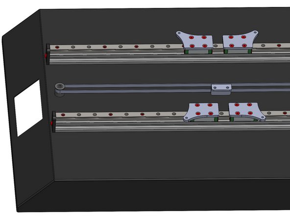
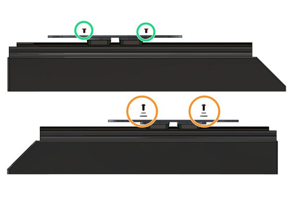
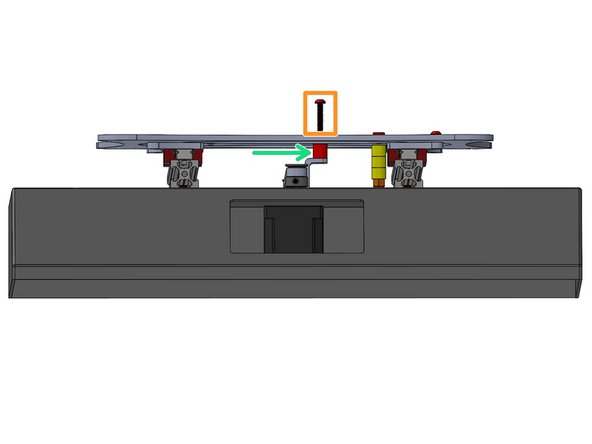
    • Remove with M5X30 SHCS one at a time

    • Replace with M5X30 BHCS

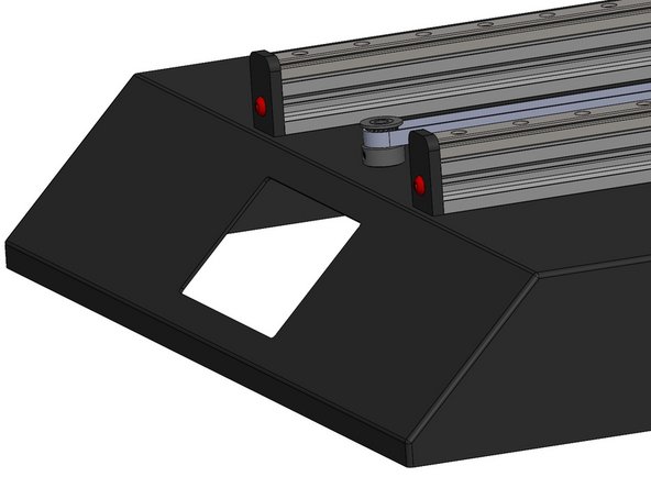
    • Slide Y carriage off from the front of the machine

  3. CR-10S PRO Y Axis Linear Rail Kit Installation, Rail Prep Instructions: passo 3, immagine 1 di 1
    • Remove from packaging

    • Note, do not touch the rail directly with your hands.

    • Wipe down rail with a lint free cloth

    • Add grease to the grease port on each side of the rail

  4. CR-10S PRO Y Axis Linear Rail Kit Installation: passo 4, immagine 1 di 3 CR-10S PRO Y Axis Linear Rail Kit Installation: passo 4, immagine 2 di 3 CR-10S PRO Y Axis Linear Rail Kit Installation: passo 4, immagine 3 di 3
    • Pre-insert Spring loaded and use an Allen wrench or screwdriver to help align

    • M3 Spring loaded T-nut

    • Use the circled Rail mounting positions

    • 16x M3x8 SHCS

    • Picture with MGN guide on rail

  5. CR-10S PRO Y Axis Linear Rail Kit Installation, Rail Adapter Plate install: passo 5, immagine 1 di 2 CR-10S PRO Y Axis Linear Rail Kit Installation, Rail Adapter Plate install: passo 5, immagine 2 di 2
    • Tighten the screws evenly in an X shape

    • 4x Adapter Plate

    • 16x M3x6 FHCS

  6. CR-10S PRO Y Axis Linear Rail Kit Installation, Stock Y carriage Plate Prep: passo 6, immagine 1 di 3 CR-10S PRO Y Axis Linear Rail Kit Installation, Stock Y carriage Plate Prep: passo 6, immagine 2 di 3 CR-10S PRO Y Axis Linear Rail Kit Installation, Stock Y carriage Plate Prep: passo 6, immagine 3 di 3
    • Remove all Vslot wheels and bolts

    • Install endstop Trigger at this location

    • Picture 2 shows endstop Trigger install

    • M5x35 SHCS

    • 3x Stock Vslot wheel spacers

    • M5 Nylon Ring Lock Nut

  7. CR-10S PRO Y Axis Linear Rail Kit Installation, Y Carriage Plate install: passo 7, immagine 1 di 3 CR-10S PRO Y Axis Linear Rail Kit Installation, Y Carriage Plate install: passo 7, immagine 2 di 3 CR-10S PRO Y Axis Linear Rail Kit Installation, Y Carriage Plate install: passo 7, immagine 3 di 3
    • Belt mounting holes goes on the right side of the priter

    • Left side screws

    • Some early kits are drilled and taped for M5 Screws. The M4x8 FHCS is substituted for a M5x10 FHCS and the M4x10 BHCS substituted for M5x10 BHCS.

    • 2x M4x8 FHCS

    • Right screw stack order

    • M4x10 BHCS - M4 washer - M4 Large OD washer

    • Tightened the left side screws first

  8. CR-10S PRO Y Axis Linear Rail Kit Installation, Belt spacer install: passo 8, immagine 1 di 3 CR-10S PRO Y Axis Linear Rail Kit Installation, Belt spacer install: passo 8, immagine 2 di 3 CR-10S PRO Y Axis Linear Rail Kit Installation, Belt spacer install: passo 8, immagine 3 di 3
    • Belt Bracket Spacer

    • 2x M4x20 SHCS

  9. CR-10S PRO Y Axis Linear Rail Kit Installation, Endstop Braket mounting hardware Change: passo 9, immagine 1 di 1
    • Remove the stock endstop bracket screw

    • Replace endstop bracket mount screw with:

    • M3x10 SHCS, M3 Washer and M3 Sliding tnut

  10. CR-10S PRO Y Axis Linear Rail Kit Installation, Rail stopper install: passo 10, immagine 1 di 2 CR-10S PRO Y Axis Linear Rail Kit Installation, Rail stopper install: passo 10, immagine 2 di 2
    • M5*10 BHCS

    • Acrylic stopper

  11. CR-10S PRO Y Axis Linear Rail Kit Installation, EndStop adjustment: passo 11, immagine 1 di 1
    • Adjust the Endstop position by sliding the endstop back until the nozzle tip lines up with the front edge of the bed when the endstop triggers.

Linea Traguardo

Altre 3 persone hanno completato questa guida.

AJ Pereira

Membro da: 05/29/20

2.652 Reputazione

16 Guide realizzate

Team

Tiny Machines 3D Membro di Tiny Machines 3D

Community

5 Membri

40 Guide realizzate

0 Commenti

Aggiungi Commento

Visualizza Statistiche:

Ultime 24 Ore: 6

Ultimi 7 Giorni: 23

Ultimi 30 Giorni: 101

Tutti i Tempi: 3,308