Introduzione
For this guide, we are using an older CR-10 Mini that has been updated with the same motherboard as a CR-10S. Start by removing the control box and placing it in a well lit place where you can sit comfortably.
Read through these steps before starting:
- Review the entire process before removing one component from your machine. You want to make sure you are comfortable and capable performing the tasks
- Confirm that you have USB connectivity with your machine. You can try to flash the mainboard firmware first. Then, if there is an issue, you still have a working machine and can resolve the USB issue before upgrading.
- Make sure you have the time and tools needed for the upgrade. It’s no fun to get halfway through a task and have to stop because you’re missing something.
-
-
Turn the power switch to OFF
-
Unplug the power cable
-
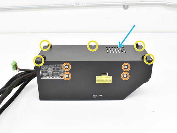
Using an M2 hex, remove the 5 button head screws holding the control box bottom cover on.
-
using an M2.5 hex, remove the 4 button head screws holding the power supply to the control box.
-
Lay the power supply to the side as shown.
-
Remove the grommet from the rear of the control box and pull back a few inches as shown.
-
-
-
With the grommet loose, you can feed harness A through the grommet with the 2 and 3 pin connector going first.
-
Leave 4-5 inches of the loose pins and reinstall the grommet.
-
-
-
After feeding harness A into the control box, note where everything is connected in case you have remove things like the LCD connections to access the new connection points.
-
Plug in the 3 pin connector to D11 row with the red wire on the V pin. For CR-10S machines, it is the pin closest to the LCD connections.
-
Plug in the 2 pin connector where the original Z end stop was plugged in. This is Z- for CR-10S machines.
-
Zip tie harness A to the original harness group for strain relief.
-
-
-
If you're going to glue the new connections in, do it now.
-
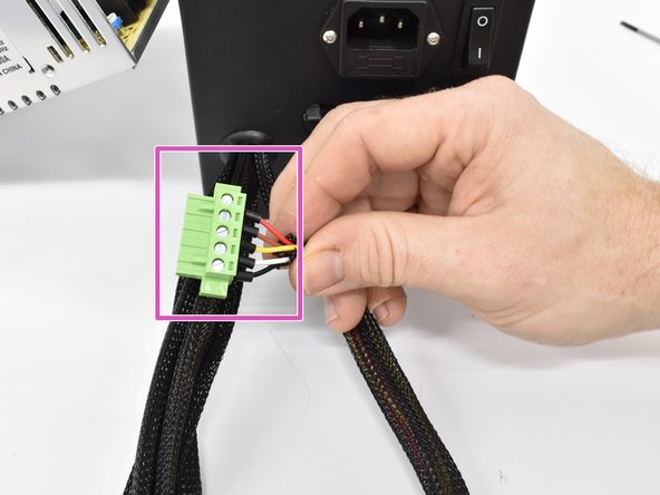
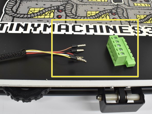
Install the male green phoenix connector onto harness A.
-
Using a flat head screwdriver, loosen the terminals 3-4 turns then insert the wires into the
-
Reinstall the power supply and tighten the screws.
-
Reinstall the bottom cover and tigthen the screws.
-
-
-
-
Reinstall the power supply and tighten the screws.
-
Reinstall the bottom cover and tigthen the screws.
-
The vent holes should be positioned over the power supply.
-
-
-
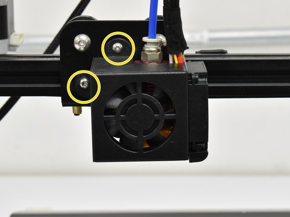
Using an M2 hex, remove the 2 button head screws holding the hot end shroud on.
-
Install the bracket using the provided M3x8 (or 3x10) screws.
-
-
-
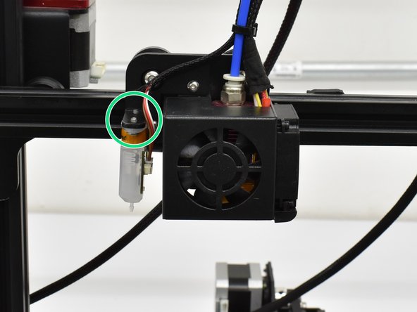
Plug the small end connector into the probe. It will only plug in one way so do not force it.
-
Install the probe as shown with the connection facting the hot end. Use an M2 hex to install the provided M3x6 screws.
-
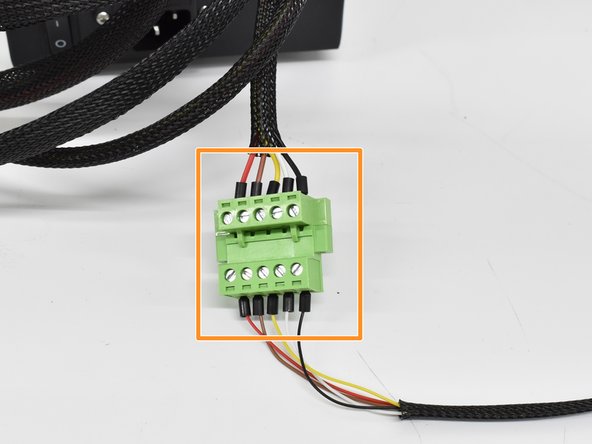
You can now install the pre-crimped wires into the phoenix connector. Match the color order from the motherboard side.
-
-
-
Double check that the colors match from the motherboard side to the probe side and plug the motherboard side into the probe side.
-
Provided zip ties can be used to attach the new harness to the original in the locations shown.
-
Be sure to leave a little slack in the probe harness so it is not pulled on when the X axis moves back and forth.
-
-
-
Please contact us regarding firmware if you have purchased our BL Touch Kit for the CR-10S.
-


To reassemble your device, follow these instructions in reverse order.
To reassemble your device, follow these instructions in reverse order.
Annulla: non ho completato questa guida.
Altre 2 persone hanno completato questa guida.

Team

6 Commenti
For the CR-10S, the 3 wire and 2 wire plug use this diagram: https://imgur.com/a/qvfqlAn. It can be hard to find the D11. Make sure the red wire is pointed towards the outside of the motherboard edge. The 2 wire plug will require you to cut the glue from the original Z connector, use a razor blade to do this. Follow the rest of the directions. The software you download and the hex file: Make sure you select the correct install as multiple come in the hex file. I only had one COM to select and the Baud was automatic. I did not plug the power cord back into the control box. I connected the box via USB and it powered on over USB. I did the firmware update like this without issue. The update took about 2 minutes and then your LCD screen will restart. Reset the items per the instructions (you will get an odd beep for each item and that's it). Once done, plug in your power cord and turn on the machine and then remove the USB. Turn machine on and Auto Home it and test the probe which should stop Z axis. Good Luck
Lastly, this is an excellent install with great customer support. Took me an hour to do while taking my time. I recommend this to anyone with a CR-10
Hi, I'm asking for help installing the CR-10S BL Touch
I assembled the wires on the motherboard and updated version 1.1.6BL_V3
The problem is that the sensor does not stop the Z axis
Thanks
Try switching the pins on the two pin z stop connector. I was wiring a CR touch and that did the trick for me. (A sharp pin or very small flathead can depress the catch and allow you to slide the wire end from the plastic bracket so you can slide them out and switch)