Questa versione può contenere modifiche errate. Passa all'ultima istantanea verificata.
Cosa ti serve
-
Questo passaggio è privo di traduzione. Aiuta a tradurlo
-
Turn off the computer and unplug the charge cable.
-
Turn the computer upside down.
-
-
Questo passaggio è privo di traduzione. Aiuta a tradurlo
-
Remove the nine Philips #00 screws holding the back panel in place (four 5.6mm, four 7.7mm, and one 9.2mm).
-
-
Questo passaggio è privo di traduzione. Aiuta a tradurlo
-
Use a plastic opening tool to gently remove the back panel.
-
-
Questo passaggio è privo di traduzione. Aiuta a tradurlo
-
Locate the motherboard under the cooling fan.
-
-
Questo passaggio è privo di traduzione. Aiuta a tradurlo
-
Unscrew the two 5.9mm screws on the PCB board with a Phillips #0 screwdriver.
-
-
Questo passaggio è privo di traduzione. Aiuta a tradurlo
-
Unscrew the four 5.9mm hard drive bracket screws with a Phillips #0 screwdriver.
-
-
Questo passaggio è privo di traduzione. Aiuta a tradurlo
-
Unscrew the four 5.9mm screws with a Phillips #0 screwdriver.
-
Next, carefully lift the LAN bracket out of the slot.
-
-
Questo passaggio è privo di traduzione. Aiuta a tradurlo
-
Remove the five 5.9mm screws holding the motherboard in place with a Phillips #0 screwdriver.
-
Remove the five 3.5mm screws holding the motherboard with a Phillips #00 screwdriver.
-
-
Questo passaggio è privo di traduzione. Aiuta a tradurlo
-
Carefully lift the motherboard up out of the slot.
-
-
-
Questo passaggio è privo di traduzione. Aiuta a tradurlo
-
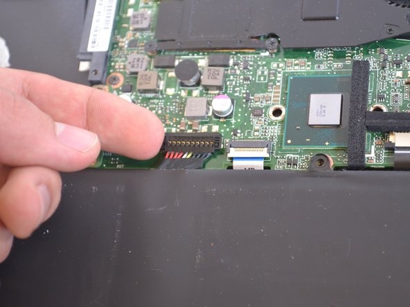
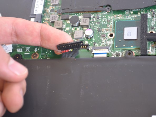
Locate and unplug the power bus from the motherboard.
-
The motherboard can now be replaced.
-
-
Questo passaggio è privo di traduzione. Aiuta a tradurlo
-
Remove the eight 4.7mm Philips #00 screws holding the battery in place.
-
-
Questo passaggio è privo di traduzione. Aiuta a tradurlo
-
The battery is attached by a set of wires.
-
Use your finger to disconnect the set of wires. It should come off very easily.
-
-
Questo passaggio è privo di traduzione. Aiuta a tradurlo
-
Disconnect the small blue TP(trackpad) labeled data bus.
-
-
Questo passaggio è privo di traduzione. Aiuta a tradurlo
-
Identify the ten 2.94mm screws on the metal bracket.
-
-
Questo passaggio è privo di traduzione. Aiuta a tradurlo
-
Unscrew the ten 2.94mm screws with the Philips #00 Head.
-
-
Questo passaggio è privo di traduzione. Aiuta a tradurlo
-
Remove all of the metallic tape holding the metal bracket to the components surrounding it.
-
-
Questo passaggio è privo di traduzione. Aiuta a tradurlo
-
Lift the metal bracket away from the laptop.
-
-
Questo passaggio è privo di traduzione. Aiuta a tradurlo
-
Unscrew the four 3.5mm screws with Phillips #00 Head.
-
This black plastic panel holds the trackpad in place.
-
-
Questo passaggio è privo di traduzione. Aiuta a tradurlo
-
Lift the trackpad up from the laptop and slide it out of the housing.
-
-
Questo passaggio è privo di traduzione. Aiuta a tradurlo
-
Unscrew the five 4.9mm screws holding the cooling fan in place using a Phillips #0 screwdriver.
-
-
Questo passaggio è privo di traduzione. Aiuta a tradurlo
-
Lift up and remove the cooling fan from the slot.
-
-
Questo passaggio è privo di traduzione. Aiuta a tradurlo
-
Next, unscrew the two 4.9mm hinge screws with a Phillips #00 screwdriver.
-
-
Questo passaggio è privo di traduzione. Aiuta a tradurlo
-
Remove the ten 4.9mm screws holding the metal keyboard panel in place, using a Phillips #00 screwdriver.
-
Carefully lift the metal keyboard panel out of the slot.
-
-
Questo passaggio è privo di traduzione. Aiuta a tradurlo
-
Pull the display hinges back in order to remove the metal keyboard panel.
-
-
Questo passaggio è privo di traduzione. Aiuta a tradurlo
-
Carefully pry and loosen the keyboard from the slot.
-
-
Questo passaggio è privo di traduzione. Aiuta a tradurlo
-
Carefully lift the keyboard out of the slot.
-


Annulla: non ho completato questa guida.
Un'altra persona ha completato questa guida.
Team

IUPUI, Team S4-G4, Wilson Summer 2017 Membro di IUPUI, Team S4-G4, Wilson Summer 2017
IUPUI-WILSON-SU17S4G4
4 Membri
7 Guide realizzate