Questa versione può contenere modifiche errate. Passa all'ultima istantanea verificata.
Cosa ti serve
-
Questo passaggio è privo di traduzione. Aiuta a tradurlo
-
Remove the eight 8.0mm Phillips #0 screws on the bottom of the laptop.
-
Remove the three 6.0mm Phillips #0 screws.
-
-
Questo passaggio è privo di traduzione. Aiuta a tradurlo
-
Open the laptop.
-
Using an iFixit opening tool, pry along the edges of the keyboard.
-
Lift the keyboard and slide it gently towards you.
-
-
Questo passaggio è privo di traduzione. Aiuta a tradurlo
-
Disconnect the two ZIF connectors by prying up the locking bar with a spudger and removing the ribbon cable.
-
-
Questo passaggio è privo di traduzione. Aiuta a tradurlo
-
Remove the six 5.6mm Phillips #0 screws around the battery.
-
-
Questo passaggio è privo di traduzione. Aiuta a tradurlo
-
Using your thumb and index finger, pinch the multi-color cable and disconnect it from the motherboard.
-
-
-
Questo passaggio è privo di traduzione. Aiuta a tradurlo
-
Unplug the black and white cable from the motherboard.
-
-
Questo passaggio è privo di traduzione. Aiuta a tradurlo
-
Peel back the tape covering the display cable.
-
Ease the cable towards the screen and out from the connector.
-
-
Questo passaggio è privo di traduzione. Aiuta a tradurlo
-
Use a Phillips #0 driver to remove the six 5mm screws on the top right and left display hinges.
-
-
Questo passaggio è privo di traduzione. Aiuta a tradurlo
-
Gently lift the display assembly up and away from the laptop.
-
-
Questo passaggio è privo di traduzione. Aiuta a tradurlo
-
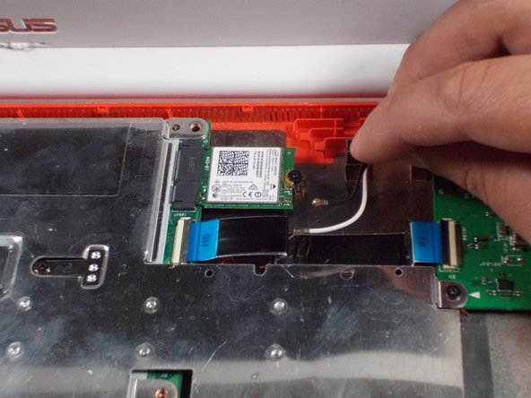
Use the spudger to pop the black and white coaxial WiFi cables up from the WiFi card.
-
-
Questo passaggio è privo di traduzione. Aiuta a tradurlo
-
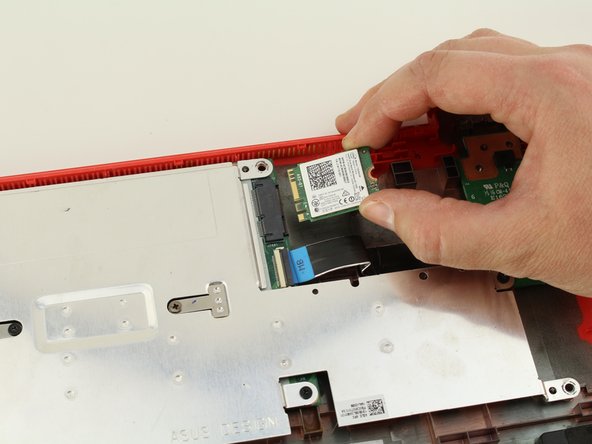
Remove the one 3.6mm Phillips #0 screw from the WiFi card.
-
Pull and lift the WiFi card away from the motherboard.
-
-
Questo passaggio è privo di traduzione. Aiuta a tradurlo
-
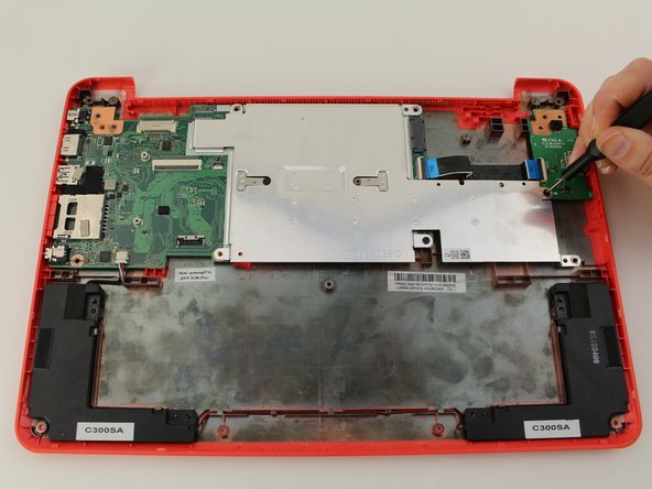
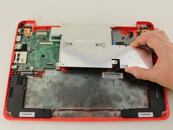
Using your Phillips #0 screwdriver, unscrew three, 3.6mm screws from the silver heatsink.
-
Remove the heatsink from the motherboard.
-
-
Questo passaggio è privo di traduzione. Aiuta a tradurlo
-
Remove the black tape from the motherboard covering the 4.2mm silver flat screw.
-
Using a Phillips #0 screwdriver, remove the 4.4mm screw on the right and the 4.2mm silver flat screw on the left from the motherboard.
-
-
Questo passaggio è privo di traduzione. Aiuta a tradurlo
-
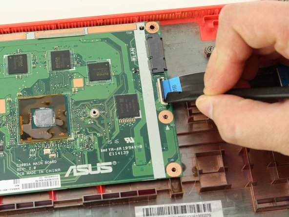
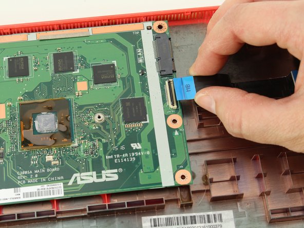
Using the black nylon spudger, unlock the black bar on the ZIF connector attached to the mid-right of the motherboard.
-
Remove the ribbon cable that attaches the motherboard to the daughterboard.
-
-
Questo passaggio è privo di traduzione. Aiuta a tradurlo
-
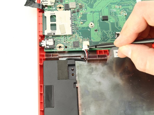
Using the black nylon spudger, carefully slide the speaker cable connector out from its attachment on the motherboard.
-
-
Questo passaggio è privo di traduzione. Aiuta a tradurlo
-
Wiggle and pull the motherboard out from the bottom case.
-