Questa versione può contenere modifiche errate. Passa all'ultima istantanea verificata.
Cosa ti serve
-
-
Appoggia il display con lo schermo rivolto verso l'alto.
-
Fai aderire 2 ventose, una per angolo del bordo superiore, e assicurati che abbiano una presa salda.
-
Il vetro è collegato al resto del display con dei piccoli magneti. Sollevalo lentamente e il vetro dovrebbe staccarsi da solo.
-
-
-
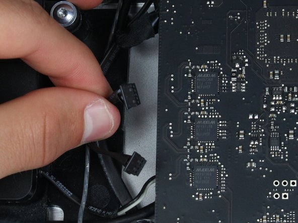
Per il prossimo cavo, che è accanto al precedente, troverai una striscia di nastro nero attaccata ad una staffa in metallo sul connettore.
-
Ruota la staffa per sbloccare il connettore, usando il nastro come manico.
-
Quindi tira lentamente il connettore per scollegarlo dalla sua presa sulla scheda.
-
-
-
Questo passaggio è privo di traduzione. Aiuta a tradurlo
-
To the left of the middle speaker (the large black component in the middle of the device), there will be a couple of wires.
-
Use the tweezers to remove the piece of tape to free the wires.
-
Next, to the right of that piece of tape is black electrical tape that needs to be removed.
-
Use the tweezers to remove the piece of black tape.
-
-
Questo passaggio è privo di traduzione. Aiuta a tradurlo
-
To the right of the middle speaker is the logic board. Here is where the three speakers in the display are connected and need to be removed.
-
-
Questo passaggio è privo di traduzione. Aiuta a tradurlo
-
To remove the right speaker, disconnect the middle of the three wires.
-
Pull carefully on the connector to release the wires from the socket in the logic board.
-
-
Questo passaggio è privo di traduzione. Aiuta a tradurlo
-
To remove the left speaker, locate the topmost connector of the three.
-
Carefully pull on the connector to release it from its socket in the logic board.
-
-
Questo passaggio è privo di traduzione. Aiuta a tradurlo
-
The bottom of the three connectors goes to the middle speaker and has both a black and white wire.
-
Carefully pull on the connector to release the wires from the socket in the logic board.
-
-
Questo passaggio è privo di traduzione. Aiuta a tradurlo
-
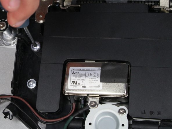
To remove the middle speaker, four screws must be removed.
-
Use the TR 10 screwdriver to remove the four screws and lift the speaker from its spot.
-
-
Questo passaggio è privo di traduzione. Aiuta a tradurlo
-
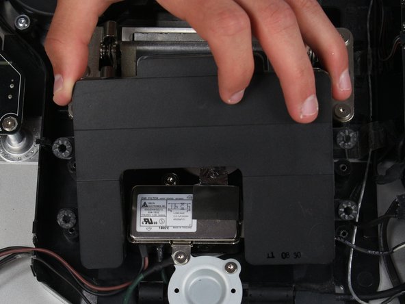
The middle speaker is now free and can be repaired/replaced!
-
-
Questo passaggio è privo di traduzione. Aiuta a tradurlo
-
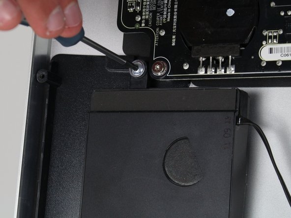
The left speaker is held in place by two screws.
-
Use the TR 10 screwdriver to free the left speaker.
-
-
Questo passaggio è privo di traduzione. Aiuta a tradurlo
-
Follow the wire coming from the left speaker and see that it is held in place by some black tape.
-
Use tweezers to remove the tape from the wire.
-
Continue following the wire and unhook it from the two built in hooks in the casing.
-
-
Questo passaggio è privo di traduzione. Aiuta a tradurlo
-
When lifting the speaker from the device, tilt it sideways to pull the speaker out from the tab on the lower right.
-
The speaker can now be replaced!
-
-
Questo passaggio è privo di traduzione. Aiuta a tradurlo
-
The right speaker is held in place by two screws (one at the top and one to the left).
-
Use the TR 10 screwdriver to remove the screws.
-
-
Questo passaggio è privo di traduzione. Aiuta a tradurlo
-
The right speaker is also held in place by two tabs (one to the bottom right and bottom left).
-
Carefully pull the speaker upwards and out, and all three speakers can be repaired!
-


Annulla: non ho completato questa guida.
Altre 7 persone hanno completato questa guida.
Team

Cal Poly, Team 5-11, Maness Spring 2015 Membro di Cal Poly, Team 5-11, Maness Spring 2015
CPSU-MANESS-S15S5G11
4 Membri
19 Guide realizzate
Un commento
Bonjour ,
J'ai un soucis sur mon écran Apple Display Thunderbolt 27" 2011 ( relié a un macbook pro retina 15" de 2015 en parfait état de fonctionnement )
L'affichage et le son se coupaient tout seul sans aucune intervention de ma part , j'ai dans l'ordre procédé à ces changement :
Changement de cable Thunderbolt/Magsafe > Problème identique
Remplacement de la carte mere ( gestion affichage/son/ports USB...) > Resolution de la coupure de l'affichage mais le SON se coupe et bascule automatiquement sur le MBPR sans possibilité de reselectionner l'Apple Display
Je ne sais pas si cela est lié mais j'ai remarqué que dans les réglages son , lorsque les HP sont fonctionnels , cela m'indique que AUDIO MONITEUR est en USB ?...
J'hesite maintenant à remplacer la carte d'alimentation 250W ou bien d'isoler chaque HP pour voir si l'un d'eux serait en cause mais je doute qu'un HP puisse mettre en défaut la sortie audio ..
Des pistes ?
Merci d'avance pour vos idées