Questa versione può contenere modifiche errate. Passa all'ultima istantanea verificata.
Cosa ti serve
-
Questo passaggio è privo di traduzione. Aiuta a tradurlo
-
Use the spudger to remove the eight black pins from the front and back of the wire screens.
-
-
Questo passaggio è privo di traduzione. Aiuta a tradurlo
-
Detach the eight secondary pins from the front and back of the wire mesh plates with a spudger.
-
-
Questo passaggio è privo di traduzione. Aiuta a tradurlo
-
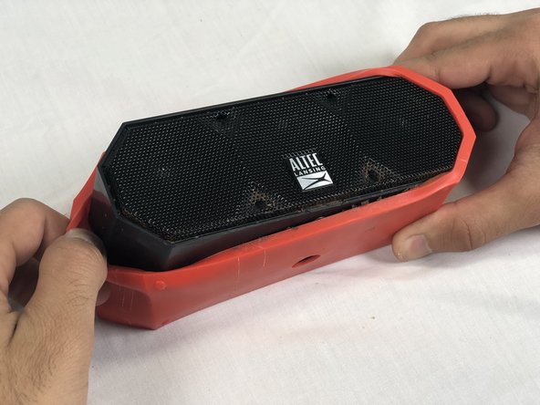
Remove both black and orange layers from the speaker body.
-
-
Questo passaggio è privo di traduzione. Aiuta a tradurlo
-
Remove the single 7.8mm Phillips #2 screw from the mounting plate located under the device.
-
Slide the mounting plate out to remove it.
-
-
-
Questo passaggio è privo di traduzione. Aiuta a tradurlo
-
Pry off the wire mesh on both sides using a metal spudger.
-
-
Questo passaggio è privo di traduzione. Aiuta a tradurlo
-
Using tweezers, remove the four rubber stoppers in each corner of the rear panel.
-
-
Questo passaggio è privo di traduzione. Aiuta a tradurlo
-
Remove the four 13.7mm Phillips #1 screws located underneath the rubber stoppers.
-
-
Questo passaggio è privo di traduzione. Aiuta a tradurlo
-
Pull the case apart to access the interior components.
-
-
Questo passaggio è privo di traduzione. Aiuta a tradurlo
-
To remove the back panel, gently pull out its wire harness.
-
-
Questo passaggio è privo di traduzione. Aiuta a tradurlo
-
Disconnect the battery from the motherboard.
-


Annulla: non ho completato questa guida.
Altre 8 persone hanno completato questa guida.
Team

USF Tampa, Team S3-G2, Nance Spring 2018 Membro di USF Tampa, Team S3-G2, Nance Spring 2018
USFT-NANCE-S18S3G2
4 Membri
4 Guide realizzate
10 Commenti
Search for MCR18650 battery. They are available.
Hickisch, I appreciate your guide on replacing this battery, but I beg to differ that replacement batteries are “available.” I keep getting sent batteries with 3-wire connectors instead of 2-wire. Plz send me a link, plz. Gracias.
for the mini life jacket 3, the motherboard is upside down so you need to remove it to unplug the battery.
For the mini life jacket 3 can you send what link you had for the battery?