Questa versione può contenere modifiche errate. Passa all'ultima istantanea verificata.
Cosa ti serve
-
Questo passaggio è privo di traduzione. Aiuta a tradurlo
-
Use the spudger to remove the eight black pins from the front and back of the wire screens.
-
-
Questo passaggio è privo di traduzione. Aiuta a tradurlo
-
Detach the eight secondary pins from the front and back of the wire mesh plates with a spudger.
-
-
Questo passaggio è privo di traduzione. Aiuta a tradurlo
-
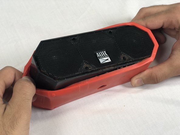
Remove both black and orange layers from the speaker body.
-
-
-
Questo passaggio è privo di traduzione. Aiuta a tradurlo
-
Remove the single 7.8mm Phillips #2 screw from the mounting plate located under the device.
-
Slide the mounting plate out to remove it.
-
-
Questo passaggio è privo di traduzione. Aiuta a tradurlo
-
Pry off the wire mesh on both sides using a metal spudger.
-
-
Questo passaggio è privo di traduzione. Aiuta a tradurlo
-
Using tweezers, remove the four rubber stoppers in each corner of the rear panel.
-
-
Questo passaggio è privo di traduzione. Aiuta a tradurlo
-
Remove the four 13.7mm Phillips #1 screws located underneath the rubber stoppers.
-
-
Questo passaggio è privo di traduzione. Aiuta a tradurlo
-
Pull the case apart to access the interior components.
-
-
Questo passaggio è privo di traduzione. Aiuta a tradurlo
-
To remove the back panel, gently pull out its wire harness.
-


Annulla: non ho completato questa guida.
Altre 4 persone hanno completato questa guida.
Team

USF Tampa, Team S3-G2, Nance Spring 2018 Membro di USF Tampa, Team S3-G2, Nance Spring 2018
USFT-NANCE-S18S3G2
4 Membri
4 Guide realizzate
9 Commenti
What do I replace once I have it apart? Where's the charging port? How do I get another charging port that works?
The charging port and the aux input are mounted to a circuit board enclosed within a small compartment on the back panel. We didn’t open the compartment in this guide because it requires breaking the seal of the compartment’s gasket, which would be unreasonable to replace. We figured it would be easier to replace the whole back panel instead. My advice for finding a new charging port would be to scour eBay or a similar site for a broken Mini Lifejacket and use its entire back panel as the replacement.
Mine has the ports on the side not the back were do i get this part
on the IMW-477-CG, the front grill covering the speakers did not have to be removed, only the back. This would potentially avoid damage to the speakers.
In my case, the micro-usb connector was separated from the board. Looks like it was surface mount soldered and power cord stress bending the connector up off the board broke it off.
The 477 also does not have connectors like in the pictures. It’s all soldered.
Where can we find a replacement back?