Questa versione può contenere modifiche errate. Passa all'ultima istantanea verificata.
Cosa ti serve
-
Questo passaggio è privo di traduzione. Aiuta a tradurlo
-
Remove the grey scuff guard at the bottom of the PC by pressing down on it, and pulling it away.
-
Lift the hinge and remove the grey rubber tabs on either side of the PC’s model information.
-
Remove the two 7.62mm Phillips #1 screws beneath the rubber tabs under the hinge and the four 7.62mm Phillips #1 screws where the scuff guard was removed.
-
Remove the two 4.74mm Phillips #1 screws under the hinge (near the hinge joints) and a 4.74mm Phillips #1 screw under the handle.
-
-
Questo passaggio è privo di traduzione. Aiuta a tradurlo
-
Use 1-2 plastic opening tools or nylon spudgers to firmly pry open the back panel.
-
-
Questo passaggio è privo di traduzione. Aiuta a tradurlo
-
Disconnect the three cables connecting the back panel ports to the motherboard.
-
Flip up the locking latch holding the two ribbon cables with a plastic opening tool and pull the cables out.
-
Gently wiggle the third connector out of its socket.
-
-
Questo passaggio è privo di traduzione. Aiuta a tradurlo
-
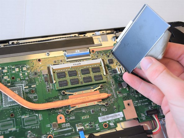
Peel off the tape attaching the metal enclosure to the heat sink.
-
Lift the metal enclosure off of the motherboard.
-
-
Questo passaggio è privo di traduzione. Aiuta a tradurlo
-
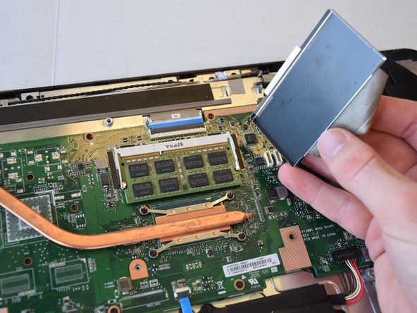
Pull the jaws of the white plastic frame apart. This will pop the front of the RAM up.
-
Gently lift the front edge of the RAM.
-
Pull the RAM out and up.
-
-
-
Questo passaggio è privo di traduzione. Aiuta a tradurlo
-
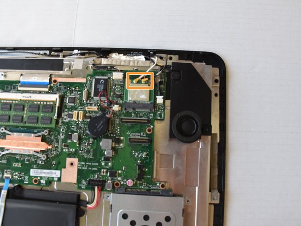
The wireless card is on the corner of the motherboard next to the speaker. Remove the black tape to reveal the wireless card.
-
-
Questo passaggio è privo di traduzione. Aiuta a tradurlo
-
Remove the 3.5 mm Phillips #1 screw from the wireless card.
-
Remove the connectors by pulling straight up on their ends.
-
-
Questo passaggio è privo di traduzione. Aiuta a tradurlo
-
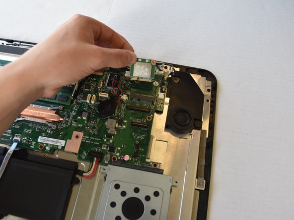
Remove the wireless card from the casing by lifting up then pulling out.
-
-
Questo passaggio è privo di traduzione. Aiuta a tradurlo
-
Remove the tape attached to the heat sink and the metal enclosure.
-
Lift the metal enclosure off.
-
-
Questo passaggio è privo di traduzione. Aiuta a tradurlo
-
Remove the four 3.0 mm Phillips #1 screws attaching the heat sink to the motherboard.
-
Remove the three 4.0 mm Phillips #1 screws connecting the fan to the device.
-
-
Questo passaggio è privo di traduzione. Aiuta a tradurlo
-
Lift the heat sink and fan assembly off of the device.
-
-
Questo passaggio è privo di traduzione. Aiuta a tradurlo
-
Flip up the locking mechanism and disconnect the three cables using a nylon spudger.
-
Disconnect two more cables by pulling back on the cable using a nylon spudger.
-
Disconnect the battery cable by pulling up on the black connector.
-
-
Questo passaggio è privo di traduzione. Aiuta a tradurlo
-
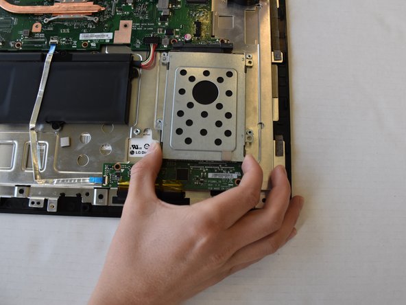
Use a Phillips #1 screwdriver to remove the four-5mm screws that hold the hard drive enclosure to the PC.
-
Pull the hard drive away from the motherboard and set it aside.
-
-
Questo passaggio è privo di traduzione. Aiuta a tradurlo
-
Use a Phillips #1 screwdriver to remove the nine-3.5mm screws located at the sides of the motherboard.
-
-
Questo passaggio è privo di traduzione. Aiuta a tradurlo
-
Lift the motherboard off the motherboard standoffs.
-


Annulla: non ho completato questa guida.
Un'altra persona ha completato questa guida.
Team

Cal Poly, Team S17-G5, Livingston Spring 2018 Membro di Cal Poly, Team S17-G5, Livingston Spring 2018
CPSU-LIVINGSTON-S18S17G5
4 Membri
16 Guide realizzate