Salta al contenuto principale

ASUS MeMO Pad 7 (ME572C) Front Camera Replacement

Cosa ti serve

  1. ASUS MeMO Pad 7 (ME572C) Front Camera Replacement, Rear Panel: passo 1, immagine 1 di 2 ASUS MeMO Pad 7 (ME572C) Front Camera Replacement, Rear Panel: passo 1, immagine 2 di 2
    • Make sure your device is turned off. Then with a plastic opening tool, carefully remove the back panel by carefully working your way around the perimeter.

    • The panel will be glued on and requires pressure to open.

  2. ASUS MeMO Pad 7 (ME572C) Front Camera Replacement: passo 2, immagine 1 di 3 ASUS MeMO Pad 7 (ME572C) Front Camera Replacement: passo 2, immagine 2 di 3 ASUS MeMO Pad 7 (ME572C) Front Camera Replacement: passo 2, immagine 3 di 3
    • After removing the rear panel, use a plastic openning tool to remove the frame of the tablet.

    • Start in the middle of the top side and insert a plastic opening tool between the screen and the frame.

    • Carefully run the plastic opening tool along all the edges of the tablet.

  3. ASUS MeMO Pad 7 (ME572C) Front Camera Replacement: passo 3, immagine 1 di 1
    • When you take the rear panel and the frame out, place the rear panel and the frame away from the device.

  4. ASUS MeMO Pad 7 (ME572C) Front Camera Replacement, Battery: passo 4, immagine 1 di 3 ASUS MeMO Pad 7 (ME572C) Front Camera Replacement, Battery: passo 4, immagine 2 di 3 ASUS MeMO Pad 7 (ME572C) Front Camera Replacement, Battery: passo 4, immagine 3 di 3
    • Disconnect the ZIF connectors to release the data cables holding the battery in. Use tweezers to do this.

    • You can also use your hand to remove ZIF connectors.

    • ZIF connectors are delicate so be careful when you are removing them.

  5. ASUS MeMO Pad 7 (ME572C) Front Camera Replacement: passo 5, immagine 1 di 1
    • Find the place where the battery connector is. Disconnect the battery connectors by carefully pulling up on them using a spudger or plastic opening tool.

  6. ASUS MeMO Pad 7 (ME572C) Front Camera Replacement: passo 6, immagine 1 di 3 ASUS MeMO Pad 7 (ME572C) Front Camera Replacement: passo 6, immagine 2 di 3 ASUS MeMO Pad 7 (ME572C) Front Camera Replacement: passo 6, immagine 3 di 3
    • Using a plastic opening tool carefully pry the battery loose. The battery is glued to the pad; slight pressure will be needed to remove the battery.

    • The casing of the battery is soft and can easily tear. Tearing can lead to the chemicals in the battery to leak out.

  7. ASUS MeMO Pad 7 (ME572C) Front Camera Replacement, Motherboard: passo 7, immagine 1 di 2 ASUS MeMO Pad 7 (ME572C) Front Camera Replacement, Motherboard: passo 7, immagine 2 di 2
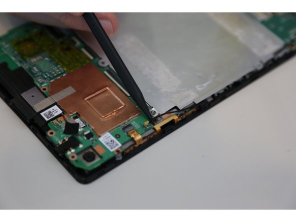
    • After removing the battery from the device, locate the volume connectors on the side of the device.

    • Using tweezers, carefully remove the volume connectors and place it to the side.

  8. ASUS MeMO Pad 7 (ME572C) Front Camera Replacement: passo 8, immagine 1 di 2 ASUS MeMO Pad 7 (ME572C) Front Camera Replacement: passo 8, immagine 2 di 2
    • Locate the GPS antenna. Pry off the GPS antenna cable with a spudger.

  9. ASUS MeMO Pad 7 (ME572C) Front Camera Replacement: passo 9, immagine 1 di 2 ASUS MeMO Pad 7 (ME572C) Front Camera Replacement: passo 9, immagine 2 di 2
    • Locate seven 2mm Phillips #0 screws attaching the motherboard to the pad. Remove the screws with a Phillips #000 screwdriver.

    • Place your screws somewhere you will remember they are at.

  10. ASUS MeMO Pad 7 (ME572C) Front Camera Replacement: passo 10, immagine 1 di 1
    • Once all the screws are taken out, you can remove the motherboard. Carefully, take the motherboard out with a plastic opening tool.

  11. ASUS MeMO Pad 7 (ME572C) Front Camera Replacement, Front Camera: passo 11, immagine 1 di 3 ASUS MeMO Pad 7 (ME572C) Front Camera Replacement, Front Camera: passo 11, immagine 2 di 3 ASUS MeMO Pad 7 (ME572C) Front Camera Replacement, Front Camera: passo 11, immagine 3 di 3
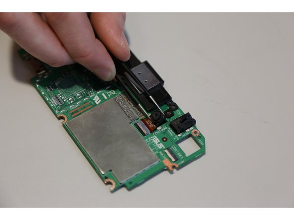
    • Flip the motherboard and find the place where the front camera connector is.

    • Using tweezers, carefully remove the front camera connectors and place it to the side.

Conclusione

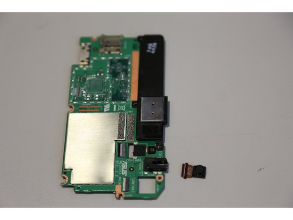
To reassemble your device, follow these instructions in reverse order.

Team

USF Tampa, Team 14-23, Meier Fall 2015 Membro di USF Tampa, Team 14-23, Meier Fall 2015

USFT-MEIER-F15S14G23

4 Membri

14 Guide realizzate

0 Commenti

Aggiungi Commento

Visualizza Statistiche:

Ultime 24 Ore: 1

Ultimi 7 Giorni: 5

Ultimi 30 Giorni: 5

Tutti i Tempi: 998